
Heat treatment part cooling device

A technology of cooling device and parts, applied in the field of heat treatment, can solve the problems of inapplicable step cooling and inconsistent temperature changes, and achieve the effect of keeping the temperature consistent and ensuring the vacuum state.

Active Publication Date: 2017-08-18
湘潭索立合金热处理有限公司
View PDF9 Cites 0 Cited by
  • Summary
  • Abstract
  • Description
  • Claims
  • Application Information

AI Technical Summary

Problems solved by technology

However, the existing cooling device is only aimed at the one-time cooling process, which does not need to consider the influence of the temperature change of the heat source on the mechanical properties of the parts during the step-wise cooling.
When using the existing cooling device for stepwise cooling, because of the temperature change of the heat source and the exchange of the gas in the device with the outside world, the temperature of the gas in contact with the parts is inconsistent, which will cause the temperature changes of the parts to be inconsistent. Therefore, the existing cooling The device is not suitable for stepwise cooling process

Method used


Image

  • Heat treatment part cooling device
  • Heat treatment part cooling device

Examples


Embodiment Construction

[0017] The present invention will be described in further detail below by means of specific embodiments:

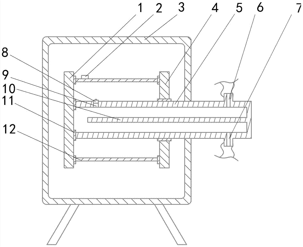
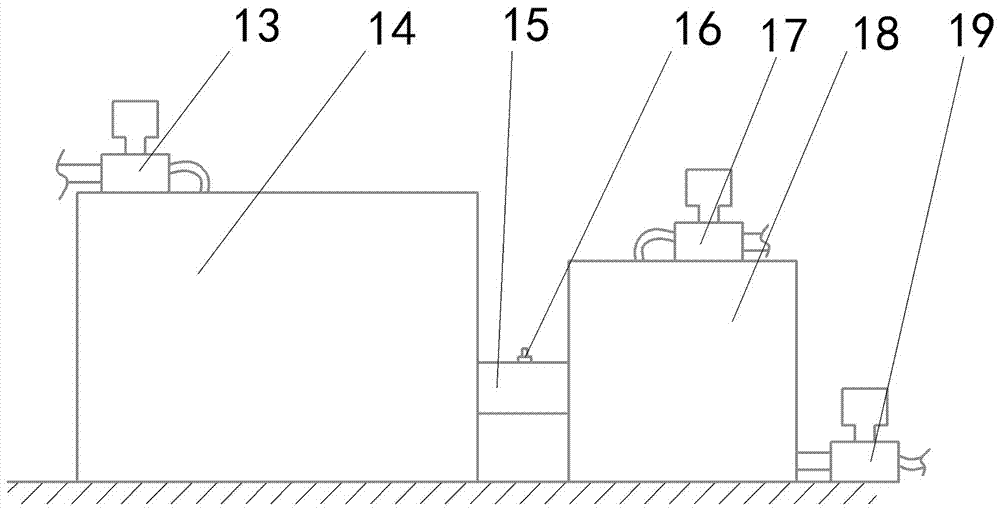
[0018] The reference signs in the drawings of the description include: the first splint 1, the first thermometer 2, the housing 3, the second splint 4, the heat source pipe 5, the third through hole 6, the fourth through hole 7, the first valve 8, the second through hole Two through holes 9, a partition 10, a seal 11, a shaft sleeve 12, a vacuum pump 13, an air tank 14, a connecting pipe 15, a second valve 16, an air pump 17, a cooling box 18, and a heat exchange pump 19.

[0019] Embodiment: the heat treatment part cooling device in this scheme, as figure 1 As shown, it includes a shell 3, a first splint 1, a second splint 4, a heat source tube 5 with one end closed, a first thermometer 2 with a pointer, a second thermometer with a pointer, an electronically controlled vacuum pump 13, and an electronically controlled vacuum pump. Air pump 17, electrically controlled hea...


PUM


Abstract

The invention belongs to the field of general heat treatment methods and devices and particularly discloses a heat treatment part cooling device. The heat treatment part cooling device comprises an outer shell, a clamp, a heat source pipe, an electronic control vacuumizing pump, an electronic control gas sending pump and an electronic control heat exchanging pump. The clamp is located in the outer shell and comprises a first clamping plate and a second clamping plate. The first clamping plate is provided with a sealing piece used for abutting against a spare part and the heat source pipe, and the second clamping plate is provided with a sealing piece used for abutting against the spare part. A first through hole is formed in the second clamping plate and provided with the sealing piece. The heat source pipe is installed in the first through hole and provided with a second through hole, a third through hole and a fourth through hole, and the second through hole is located in the side, close to the first clamping plate, of the second clamping plate and provided with an electric first valve. According to the heat treatment part cooling device, part of gas is fixed between the spare part and the heat source pipe, gas with the volume being fixed is used as a heat exchanging medium, good diffusivity of the gas is used for cooling the spare part, and consistent temperature changing of all places in the spare part is ensured.

Description

technical field [0001] The present invention belongs to the field of general methods or equipment for heat treatment. Background technique [0002] The heat treatment method of high temperature tempering after quenching is called quenching and tempering treatment. Generally, tempering only needs to be kept at one temperature for a certain period of time, but in order to meet certain physical characteristics of the parts, a stepwise cooling is required after tempering, that is, when the temperature drops to a certain temperature, keep it for a period of time, and then lower the temperature to the next temperature and keep it for a period of time , and so on until it drops to room temperature. This treatment method can greatly adjust the performance and material of steel, and its strength, plasticity and toughness are all good, and it has good comprehensive mechanical properties. At this time, the ferrite has basically no carbon supersaturation, and the carbide is also a sta...

Claims


Application Information

Patent Timeline
IPC IPC(8): C21D1/25C21D1/773C21D9/00C21D11/00
CPCC21D1/25C21D1/773C21D9/0062C21D11/005
Inventor 涂金华张成伟孙少辉王朝军
Owner 湘潭索立合金热处理有限公司
Learn More