A horizontal single-axis directional rotary-impact combined excavation type engineering slotting machine

A tunneling and grooving machine technology, which is applied to earth moving machines/shovels, construction, etc., can solve the problems of difficulty in improving tunneling efficiency, a large proportion of engineering costs, and damage to excavation components, so as to improve tunneling efficiency and optimize tunneling. Efficiency, the effect of reducing tooth wear

Active Publication Date: 2022-07-05
项栋才 +1
View PDF5 Cites 0 Cited by
  • Summary
  • Abstract
  • Description
  • Claims
  • Application Information

AI Technical Summary

Problems solved by technology

However, the inventor has found several problems in the practical research: 1. The above-mentioned slotting machine adopts the milling shaft periodical reversing process to balance the milling reaction force, although it can solve the problem that the rock and soil reaction force drives the whole The frame deviates from the vertical direction, but due to the periodic reversing of the milling axis, it is difficult to take into account the different rotation directions of the cutter teeth on the rotating milling axis. It is difficult to improve the excavation efficiency and increase the wear of the cutter teeth by adopting a reasonable angle and shape. , cutter tooth wear accounts for a large proportion of project cost
On the one hand, this punching method has no pre-applied drilling pressure, and the rock-breaking effect is poor. On the other hand, if the punching intensity is too high, it is easy to damage the excavation parts. The frequency is not high, so the excavation efficiency is greatly limited

Method used


Image

  • A horizontal single-axis directional rotary-impact combined excavation type engineering slotting machine
  • A horizontal single-axis directional rotary-impact combined excavation type engineering slotting machine
  • A horizontal single-axis directional rotary-impact combined excavation type engineering slotting machine

Examples


Embodiment 1

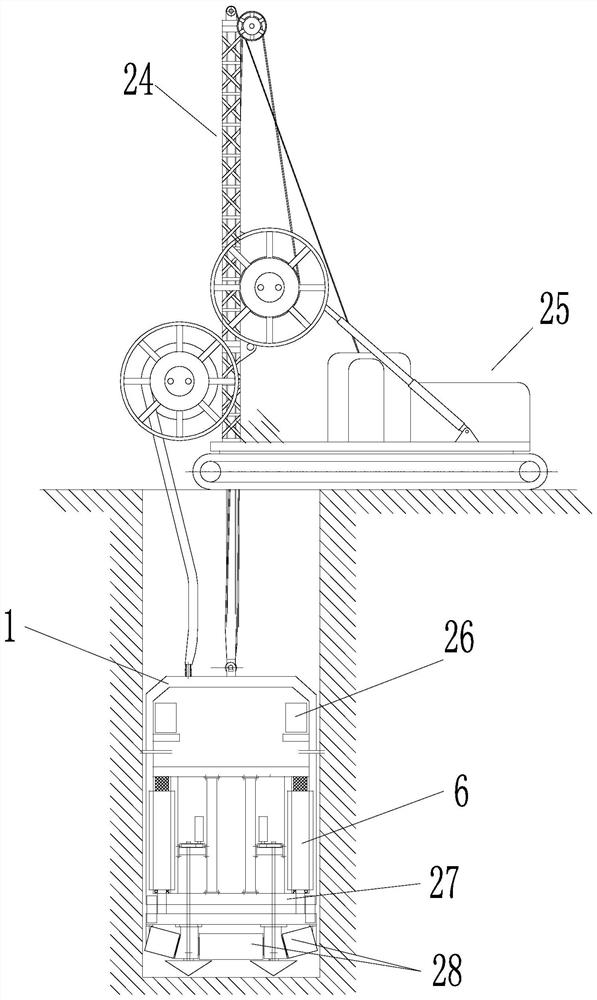
[0047] like Figure 1 to Figure 5 As shown in the figure, the horizontal single-axis directional rotary-impact combined tunnel-type engineering grooving machine in this embodiment includes a traveling device 25 with a hoisting device 24 and a power system, and a monitoring device (not shown in the figure); the hoisting device 24 A symmetrically arranged impact milling device is suspended from the traction end. The impact milling device includes a vertical guide frame 1, a deviation correction device 26, a milling shaft 28 with a milling tool, and an impact device. The impact device is a vertical high-frequency hydraulic impact hammer. 6. The axis of the milling shaft 28 is located in the plane where the guide frame 1 is located, and is arranged horizontally; the milling shaft 28 is driven by the vertical hydraulic motor 4 through the reversing device 10, and the milling shaft 28 has a segmented balanced counter-rotation directional rotation In the milling state, the connecting...

Embodiment 2

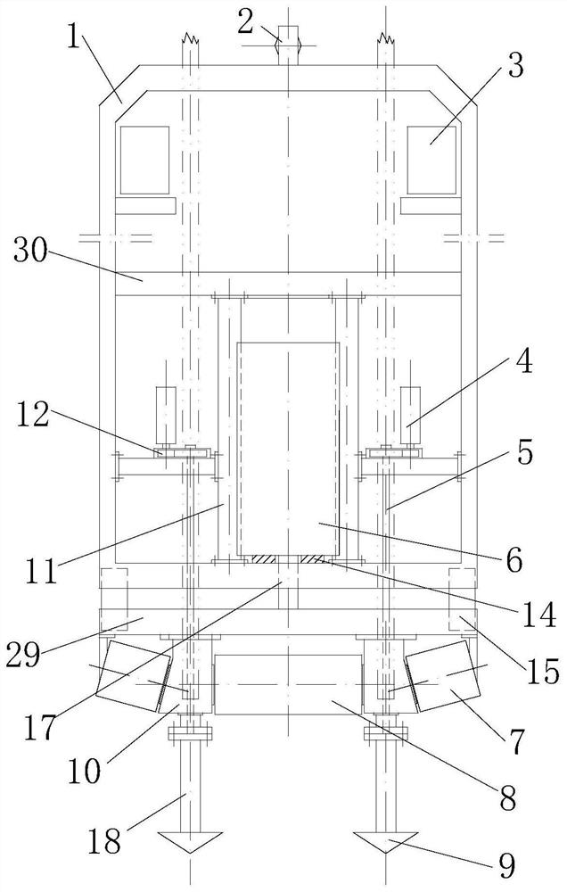
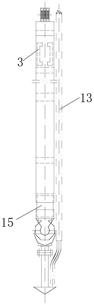
[0056] The difference between this embodiment and Embodiment 1 is that, such as Figure 8 and Figure 9 As shown, the impact device is two smaller impact hammers 6 , and the impact hammers 6 are arranged outside the hydraulic motor 4 and its gearbox 12 . The top end of the impact hammer 6 and the middle beam 30 of the guide frame 1 are fixedly connected through the buffer device 16, and a vertical beam is provided between the bottom beam 27 of the guide frame 1 and the middle beam 30, and the vertical beams on both sides of the impact hammer 6 There is a slideway 11 on it, so that the impact hammer 6 slides up and down along the slideway 11 .

[0057] The milling tool is a cutter tooth base 23 protruding outward, the cross section of the cutter tooth base 23 is a convex arc surface, and the top of the convex arc surface is inlaid with cutter teeth (see Figure 12 and Figure 13 ).

Embodiment 3

[0059] The milling shaft 28 includes a plurality of three-axis symmetrical balance structures combined in parallel, and the milling range of the upper end of the inclined milling shaft covers the bottom surface of its supporting column.

[0060] Compared with the previous slotting machine, the present invention has the following advantages:

[0061] 1. The suspension guide frame 1 is adopted, which cancels the travel drill pipe from the ground to the bottom of the groove, and omits the process of connecting the drill pipe, which makes the excavation device move easily, the whole machine is flexible, and avoids the easy breakage of the rigid double drill pipe. , buried drilling and other accidents.

[0062] 2. Using single-axis milling, compared with double-wheel milling, the thickness of the entire guide frame 1 and the milling device can be further reduced, so that narrower grooves can be cut (narrow grooves with a thickness of only less than 30cm can be cut). In many practi...


PUM


Abstract

The invention relates to a horizontal single-axis directional rotary-impact combined excavation type engineering grooving machine, including a traveling device with a hoisting device and a power system and a monitoring device; an impact milling device is suspended at the traction end of the hoisting device, and the impact milling device includes a vertical Directional guide frame, rectifying device, milling shaft, impact device; the axis of the milling shaft is located in the plane of the guide frame, and is arranged horizontally or obliquely, driven by the horizontal hydraulic motor or the vertical hydraulic motor through the reversing device. , the milling shaft has a directional rotation milling state of segmental balance and reverse rotation, and the impact device is placed in the guide frame; the connecting beam above the milling shaft is hung under the bottom beam of the guide frame through a suspension sliding device, and the drill rod of the impact device is attached to the bottom beam of the guide frame. The impact on the connecting beam and the milling axis and the positioning drill bit is driven by hydraulic pressure. The invention can conditionally select the direction and angle of the cutting edge, and can quickly change the excavation mode according to the stratum lithology, so as to obtain higher excavation efficiency and reliability.

Description

technical field [0001] The invention relates to a horizontal single-axis directional rotary-impact combined excavation type engineering slotting machine, which belongs to the technical field of slotting equipment. Background technique [0002] According to the inventor's understanding, in the fields of water conservancy, transportation, construction and other engineering fields, it is necessary to build various underground continuous walls under different geological conditions. In the actual construction process, it is a very difficult and unsolved problem to open deep grooves to build various underground continuous walls in the strata containing gravel, boulders, boulders and hard rock layers. The slotting machine that has been developed by the inventor can complete the slotting operation with high efficiency and low cost, and the effect is good. [0003] The inventor applied for a Chinese invention patent on April 13, 2015 (application number 201510173686.9, authorization...

Claims


Application Information

Patent Timeline
Patent Type & Authority Patents(China)
IPC IPC(8): E02F5/08E02F5/14
CPCE02F5/08E02F5/14
Inventor 刘农
Owner 项栋才
Why Eureka
Try Eureka