SCR catalytic silencer device

A technology of catalytic muffler and protection device, applied in muffler device, exhaust device, machine/engine, etc., can solve the problems of insufficient mixing of exhaust gas and urea, easy breakage of urea pipeline joints, small exhaust gas flow, etc., so as to reduce urea Crystallization risk, reduction of crystallization risk, effect of faster flow rate

Inactive Publication Date: 2017-08-18
WEICHAI POWER CO LTD +1
View PDF5 Cites 8 Cited by
  • Summary
  • Abstract
  • Description
  • Claims
  • Application Information

AI Technical Summary

Problems solved by technology

Moreover, there are strict requirements on the installation angle of the nozzle of the traditional structure SCR tank, which must be at least above the horizontal plane, and the layout of the whole vehicle is severely restricted; moreover, the urea nozzle is exposed outside the tank, and the urea pipe joint is easily broken during transportation and use, resulting in a failure rate high
Therefore, there is an urgent need to solve the problem of insufficient mixing of exhaust gas and urea caused by the small exhaust gas flow rate and low flow rate of medium-sized displacement engines, resulting in serious crystallization.

Method used


Image

  • SCR catalytic silencer device
  • SCR catalytic silencer device
  • SCR catalytic silencer device

Examples


Embodiment 1

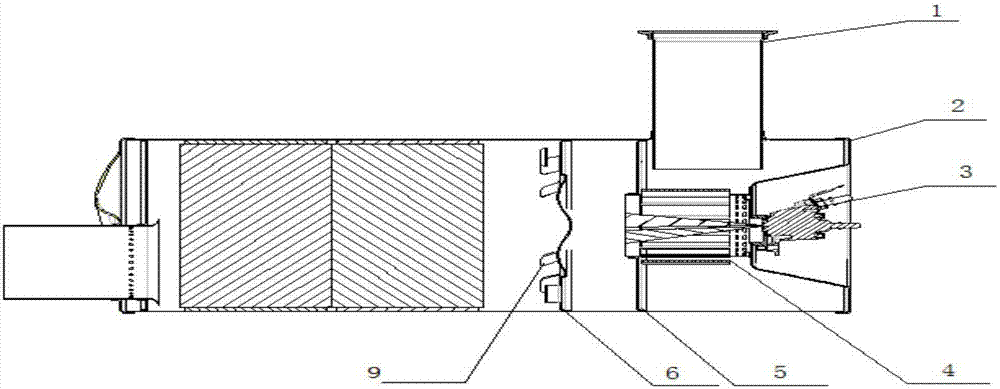
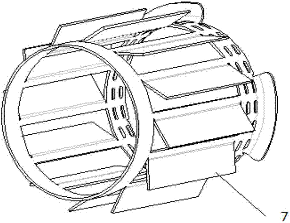
[0022] An SCR catalytic muffler device, including an intake pipe 1 and a urea nozzle 3, and also includes a nozzle protection device 2 and a first-stage swirler 4; the nozzle protection device 2 is a front end cover with a concave structure, and the urea nozzle 3 The end is flush with the edge of the front end cover, and the outer wall of the first-stage swirler 4 is provided with a plurality of first blades 7 arranged in an oblique arrangement at uniform intervals, and there is a gap between the plurality of first blades 7 gap, each of the first blades 7 is a blade of the same airfoil, see figure 2 The urea nozzle 3 is vertically installed on the upper surface of the concave structure of the front end cover, the first-stage cyclone 4 is installed on the lower surface of the concave structure of the front end cover, and the air intake pipe 1 Through the outer wall of the SCR box and the outlet direction of the intake pipe 1 is perpendicular to the axial direction of the first...

Embodiment 2

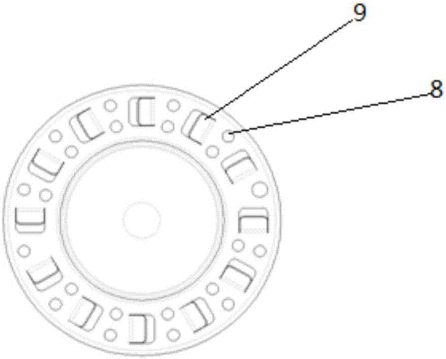
[0024] A kind of SCR catalytic muffler device, see figure 1 , comprising an air intake pipe 1, a urea nozzle 3, a nozzle protection device 2, a first-stage swirler 4, a front baffle 5 and a second-stage swirler 6; the nozzle protection device 2 is a front end cover with a concave structure, and the The end of the urea nozzle 3 is flush with the edge of the front end cover, and the outer wall of the first-stage cyclone 4 is provided with a plurality of first blades 7 arranged obliquely at even intervals, and the plurality of first There is a gap between the blades 7; the surface of the two-stage cyclone 6 has small holes 8 with different pitches and is provided with a plurality of second blades 9, wherein each small hole 8 is a circular hole with the same diameter, and each The second blade 9 is the blade of the same airfoil, see image 3 . The urea nozzle 3 is vertically installed on the upper surface of the concave structure of the front end cover, the first-stage cyclone 4...


PUM


Abstract

The invention provides a SCR catalytic silencer device. The device comprises an intake pipe and an urea nozzle, and further comprises a nozzle protection device and a first-grade cyclone; the nozzle protection device is a front end cover with an inward concave structure; multiple first blades are uniformly inclined on the outer wall of the first-grade cyclone at intervals, and are provided with gaps; the urea nozzle is vertically mounted on the upper surface of the inward concave structure of the front end cover; the first-grade cyclone is mounted on the lower surface of the inward concave structure of the front end cover; the intake pipe penetrates through the outer wall of a SCR box; and an outlet direction of the intake pipe is perpendicular to the axial direction of the first-grade cyclone, so that engine-exhausted gas fed from the intake pipe is fed in a pipe of the first-grade cyclone by the gaps of the multiple first blades.

Description

technical field [0001] The invention relates to a muffler device, in particular to an SCR catalytic muffler device. Background technique [0002] SCR technology is one of the main post-treatment technologies for eliminating nitrogen oxides in diesel engine exhaust. SCR technology needs catalyst assistance to eliminate nitrogen oxides (NOx). The catalyst is coated on the carrier, and special materials and structures are added to the carrier. It is designed to play the role of noise reduction, and after the packaging is completed, it is called the SCR catalytic muffler. [0003] The SCR catalytic noise reduction system is mainly divided into three parts according to the function: the control unit, the urea dosage unit and the catalytic reaction unit. Among them, the control unit of the SCR system is integrated with the engine control unit (ECU), collectively referred to as the control unit, which is mainly used to implement the SCR control strategy, and according to the ambie...

Claims


Application Information

Patent Timeline
Patent Type & Authority Applications(China)
IPC IPC(8): F01N3/20F01N3/28
CPCF01N3/2066F01N3/28F01N3/2892Y02T10/12
Inventor 闫娟郎俊宇王奉双李俊普刘兴龙
Owner WEICHAI POWER CO LTD
Why Eureka
Try Eureka