
Extender engine cooling water cavity structure

A technology for cooling water cavity and engine, which is applied in the direction of engine cooling, machine/engine, engine components, etc. It can solve the problems of small contact area between cooling water and cylinder block, reduced overall service life of the engine, and low cooling water heat. , to achieve the effect of lowering the operating temperature, increasing the service life and increasing the water storage volume

Inactive Publication Date: 2017-08-18
CHONGQING JIANSEN POWER MACHINERY
View PDF0 Cites 0 Cited by
  • Summary
  • Abstract
  • Description
  • Claims
  • Application Information

AI Technical Summary

Problems solved by technology

The water channel of the cylinder body of the water-cooled engine currently on the market is a spiral water channel. There is no heat dissipation structure in the water channel, and it is only a water flow channel. Therefore, the contact area between the cooling water and the cylinder block is very small, and the heat taken away by the cooling water from the cylinder block is small. Too much, making it difficult for the engine to cool down during operation, and the overall service life of the engine is reduced

Method used


Image

  • Extender engine cooling water cavity structure
  • Extender engine cooling water cavity structure

Examples


Embodiment

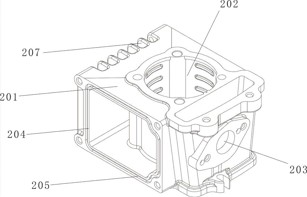
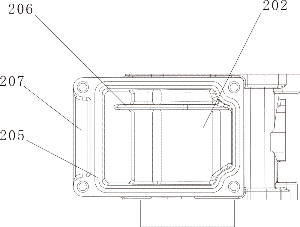
[0015] Depend on figure 1 and figure 2 As shown, a cooling water chamber structure of a range extender engine includes a cold water chamber 201 and a cylinder liner 202 arranged in the cold water chamber 201; a water inlet 203 and a water outlet window 204 are arranged on the cold water chamber 201, and the water outlet window 204 A sealing groove 205 is also provided along the edge of the window on the outer side of the cylinder liner 202 for installing sealing components; an inner cooling fin 206 is arranged on the side wall of the cylinder liner 202, and the inner cooling fin 206 is installed on the upper position of the side wall of the cylinder liner 202, Its sheet structure is parallel to the bottom surface of the cold water chamber 201, and the inner heat sink 206 is installed on all parts of the cold water chamber 201 along the circumference of the side wall of the cylinder liner 202, and the installation position of the inner heat sink 206 is close to the cylinder bl...


PUM


Abstract

The invention relates to an extender engine cooling water cavity structure which comprises a cold water cavity and a cylinder sleeve arranged in the cold water cavity. The cold water cavity is provided with a water inlet and a water outlet window. The outer side of the water outlet window is further provided with a sealing groove which is used for mounting a sealing part. The side wall of the cylinder sleeve is provided with an inner cooling fin. The outer surface of the cold water cavity is provided with outer cooling fins. By adoption of the extender engine cooling water cavity structure, a cylinder is internally provided with the inner cooling fin, the cooling area is effectively increased, and meanwhile, the water storage volume of the cold water cavity is increased so that cooling water can take more heat out of the cylinder, the operation temperature of an engine is effectively lowered, and the service life of the engine is prolonged.

Description

technical field [0001] The invention belongs to the field of range extender engines, in particular to a cooling water chamber structure for a range extender engine. Background technique [0002] A range extender usually refers to a kinetic energy device that can provide additional electric energy to help electric vehicles or electric equipment extend the running time. Ordinary range extenders are usually composed of an engine and a generator; the engine part of the range extender is different from the The fuel engine used alone is especially limited by the volume and weight and the use environment. The range extender engine generally has a small displacement and low power, which is different from ordinary fuel engines in structure and function. The water channel of the cylinder body of the water-cooled engine currently on the market is a spiral water channel. There is no heat dissipation structure in the water channel, and it is only a water flow channel. Therefore, the co...

Claims


Application Information

Patent Timeline
Patent Type & Authority Applications(China)
IPC IPC(8): F01P3/04F02F1/06
CPCF01P3/04F01P2003/022F02F1/06
Inventor 刘涛
Owner CHONGQING JIANSEN POWER MACHINERY
Learn More