Draining pump rotor starting mechanism, draining pump motor and draining pump

A technology of starting mechanism and drainage pump, applied in electromechanical devices, machines/engines, liquid fuel engines, etc., can solve noise, poor concentricity between rotor bushing x23 and injection core x21, rotor starting mechanism x2 starting performance limitation, etc. problems, to achieve the effect of enhancing concentricity, improving starting performance, and prolonging service life

Pending Publication Date: 2017-08-18
HANYU GRP CO LTD
View PDF5 Cites 0 Cited by
  • Summary
  • Abstract
  • Description
  • Claims
  • Application Information

AI Technical Summary

Problems solved by technology

[0003] However, since the rubber columns (x24 and x25) are in the state of being compressed and elastically deformed during the rotation of the rotor starting mechanism x2, the rubber columns (x24 and x25) will radially impact the rotor sleeve x23 and the injection molding The magnetic core x21 produces a certain force, so the rotor sleeve x23 and the injection molded magnetic core x21 will be biased under the elastic force, resulting in poor concentricity between the rotor sleeve x23 and the injection molded magnetic core x21, and the rotor shaft x22 Improper eccentricity will also cause certain noise and will greatly reduce the service life of the rotor shaft x22 and bearings
[0004] In addition, due to

Method used


Image

  • Draining pump rotor starting mechanism, draining pump motor and draining pump
  • Draining pump rotor starting mechanism, draining pump motor and draining pump
  • Draining pump rotor starting mechanism, draining pump motor and draining pump

Examples


Embodiment Construction

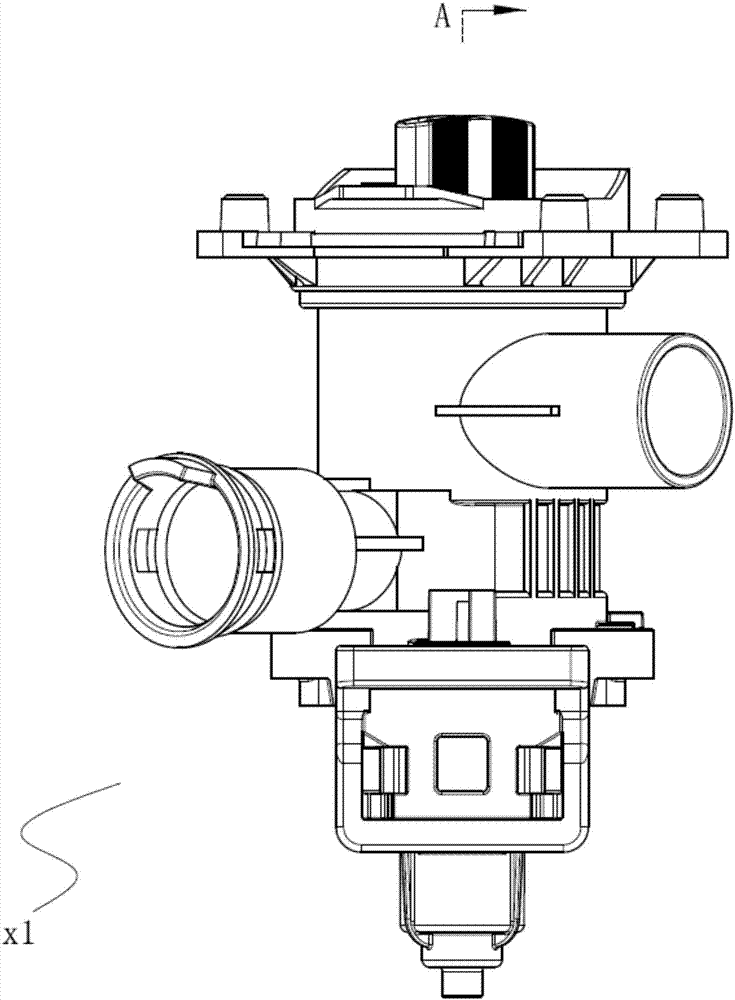
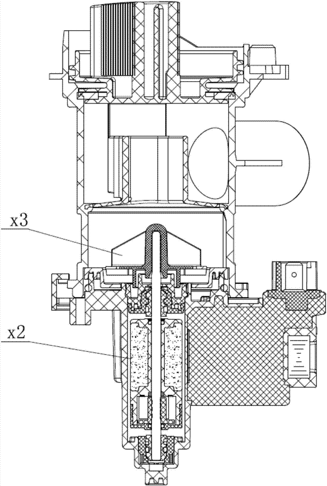
[0039] The invention provides a drainage pump, which includes a pump body, a pump cover assembly sealingly connected with the pump body, a drainage pump motor, and an impeller. The drainage pump motor includes a plastic-encapsulated coil, a stator core and other related components arranged outside the pump body, and a drainage pump rotor starting mechanism arranged in the pump body and coaxially connected with the impeller. Because in the present invention, only the drainage pump rotor starting mechanism in the drainage pump motor is improved, and other structures in the drainage pump except the drainage pump rotor starting mechanism are the same as the corresponding structures in the prior art drainage pump, so in The structure of other parts of the drainage pump except the rotor starting mechanism of the drainage pump will not be described in detail.

[0040] see Figure 8 ~ Figure 10 Specifically, the drainage pump rotor starting mechanism 2 includes a magnetic core 21 , a...


PUM


Abstract

The invention relates to a draining pump rotor starting mechanism, a draining pump motor and a draining pump. The draining pump rotor starting mechanism comprises a magnetic core, a rotor shaft, a rotor shaft sleeve and a shock absorption body, wherein a cylindrical surface wall is arranged in a starting cavity of the magnetic core; the outer side surface of the cylindrical surface wall is partially connected with the inner wall of the starting cavity through a starting rib; an accommodating cavity for accommodating the shock absorption body is formed in a space between the outer side surface, which is not connected with the starting rib, in the cylindrical surface wall and the inner wall surface of the starting cavity to which the outer side surface faces; the shock absorption body can be driven by the starting rib to slide in the accommodating cavity; and the sliding shock absorption body drives the rotor shaft to rotate through a transmission rib. Therefore, the draining pump rotor starting mechanism can guarantee the concentricity of all components during rotation, optimize the noise reducing effect and prolong the service life; and meanwhile, the acceleration angle stroke can be increased, and the starting performance of the starting mechanism can be greatly improved.

Description

technical field [0001] The invention relates to the technical field of motors, in particular to a drainage pump rotor starting mechanism, a drainage pump motor and a drainage pump. Background technique [0002] Currently, see Figure 1 to Figure 6 The drainage pump motor of the washing machine drainage pump x1 generally adopts a U-shaped stator iron core permanent magnet synchronous motor capable of self-starting. Rotor bushing x23. The rotor sleeve x23 and the injection-molded magnetic core x21 are axial hole clearance fit, and the outer wall of the tubular main body of the rotor sleeve x23 protrudes to form a transmission rib x231; the injection-molded magnetic core x21 has a housing for the rotor sleeve In the starting cavity of x23, the inner wall of the starting cavity protrudes to form a starting rib x211. There will be interference between the driving rib x231 and the starting rib x211 to form two sets of interference surfaces, and a rubber column (x24 and x25) is i...

Claims


Application Information

Patent Timeline
IPC IPC(8): F04D13/06F04D29/66H02K7/118H02K5/24
CPCH02K5/24H02K7/118F04D13/06F04D29/669
Inventor 王红标邓海锋徐飞
Owner HANYU GRP CO LTD
Why Eureka
Try Eureka