Natural gas liquefaction method and device

A liquefaction device and natural gas technology, applied in the field of natural gas liquefaction, can solve problems such as high pressure, heat exchanger damage, and unstable structure, and achieve the effect of effective liquefaction process, improved efficiency, and simple equipment

Inactive Publication Date: 2017-08-18
延安国能科技股份有限公司
View PDF7 Cites 2 Cited by
  • Summary
  • Abstract
  • Description
  • Claims
  • Application Information

AI Technical Summary

Problems solved by technology

However, the structure of the existing heat exchanger is not stable enough. When the gas-liquid mixture enters through the compressor, the pressure is relatively high, which is easy to cause damage to the heat exchanger.

Method used


Image

  • Natural gas liquefaction method and device
  • Natural gas liquefaction method and device
  • Natural gas liquefaction method and device

Examples


Embodiment 1

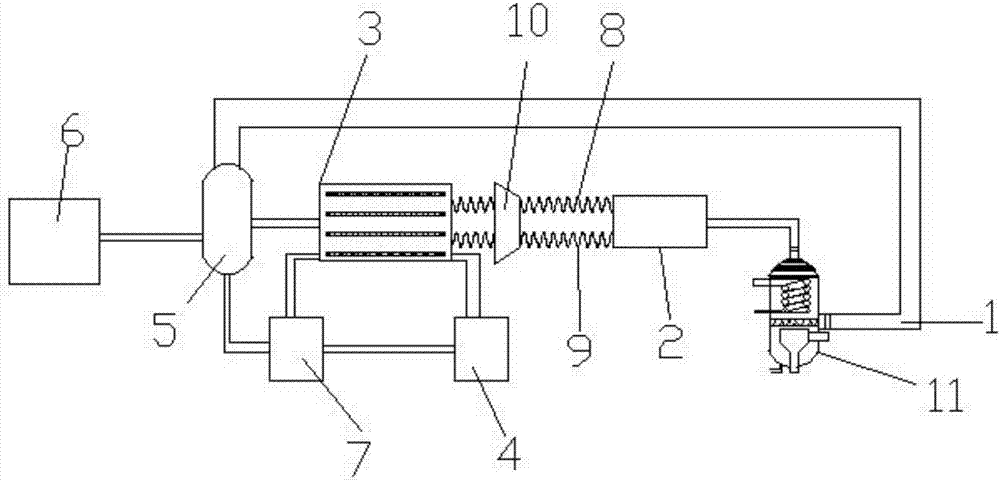
[0040] Refer to attached figure 1 As shown, a natural gas liquefaction device described in this embodiment includes a natural gas inlet pipeline 1, a compressor 2, a heat exchanger 3, a liquid nitrogen storage tank 4, a gas-liquid separator 5, and a liquefied natural gas storage tank 6 , the natural gas inlet pipeline 1 is connected to the compressor 2, the liquid nitrogen storage tank 4 and the compressor 2 are respectively connected to the input end of the heat exchanger 3, and the output ends of the heat exchanger 3 are respectively It is connected with the liquid nitrogen recovery box 7 and the gas-liquid separator 5, and the liquid nitrogen recovery box 7 is connected with the liquid nitrogen storage tank, forming a circulation pipeline as a whole, which is beneficial to the repeated use of liquid nitrogen. Wherein, the gas outlet of the gas-liquid separator 5 communicates with the natural gas inlet pipeline 1, so that the separated gas enters the natural gas inlet pipeli...

Embodiment 2

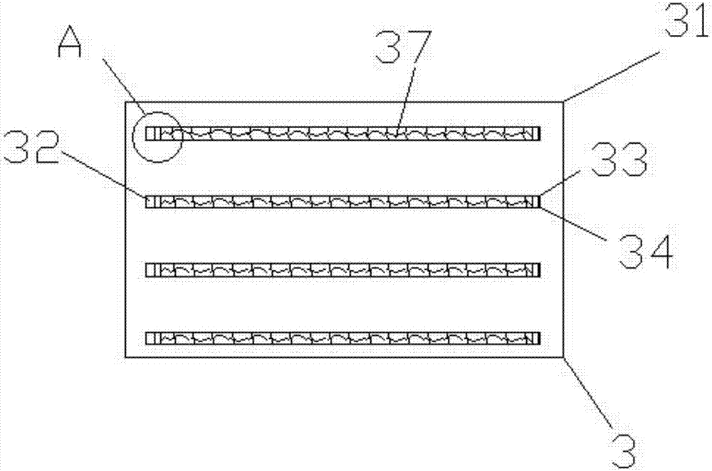
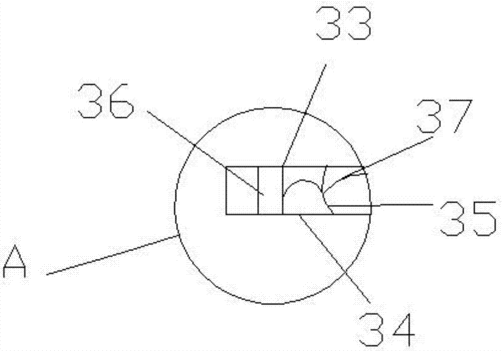
[0044] Refer to attached figure 2 As shown, as a further improvement of the above embodiment, a polyurethane foam layer (not shown in the figure) is provided between the shell 31 of the heat exchanger 3 and the first partition 33 and / or the second partition 34 ;

[0045] Further, when the topmost part of the casing 31 is provided with the first partition 33, the thickness of the polyurethane foam layer is the same as the distance between the inner wall of the casing 31 and the first partition 33; when the bottommost part of the casing 31 is provided with During the second dividing plate 34, then the thickness of polyurethane foam layer is identical with housing 31 bottom insides and the spacing of the second dividing plate 34; Of course, if above-mentioned change the second dividing plate 34 or The principle of the first partition 33 is the same.

[0046] The thermal conductivity of the foamed polyurethane layer is very low, which can reduce the heat loss of the heat exchan...

Embodiment 3

[0051] Refer to attached figure 1 As shown, as a further improvement of Embodiment 1, in this embodiment, the compressor 2 is connected to the heat exchanger 3 through the parallel first spiral hose 8 and the second spiral hose 9, and the first A tapered connecting pipe 10 is provided between the first spiral hose 8 and the second spiral hose 9 .

[0052] Due to the impact of the compressed air pulse in the compressor 2, it will cause damage to the fins 35 in the heat exchanger 3, so the flow is shunted out through the spiral hose and buffered by the conical connecting pipe 10, which can reduce the impact and effectively protect the fins 35.


PUM


Abstract

The invention discloses a natural gas liquefaction method and a device. The method comprises the following steps: (a) natural gas compression pretreatment: raw material natural gas is pretreated through a compressor until the natural gas is liquefied; (b) high-pressure resisting heat exchange: the natural gas treated by compression and liquid nitrogen in a liquid nitrogen storage tank exchange heat in sequence through a heat exchanger; and after the natural gas is cooled, mixed liquid is obtained; (c) separation of the mixed liquid: the mixed liquid obtained after heat exchange is separated in a gas-liquid separator to obtain liquefied natural gas; and (d) circulation of the liquid nitrogen: the liquid nitrogen after heat exchange flows into the liquid nitrogen storage tank again by a liquid nitrogen recovery box.

Description

technical field [0001] The invention belongs to the technical field of LNG preparation devices, and in particular relates to a natural gas liquefaction method and device. Background technique [0002] Liquefied Natural Gas (LNG), whose main component is methane, is recognized as the cleanest energy on earth. Colorless, odorless, non-toxic and non-corrosive, its volume is about 1 / 625 of the volume of the same volume of gaseous natural gas, and the weight of liquefied natural gas is only about 45% of the same volume of water. The manufacturing process is to first purify the natural gas produced in the gas field, and then transport it by liquefied natural gas ship after a series of ultra-low temperature liquefaction. The burning of liquefied natural gas causes very little air pollution and releases a lot of heat, so liquefied natural gas is a relatively advanced energy source. [0003] In the prior art, the liquefaction of natural gas is mainly to turn natural gas and refrige...

Claims


Application Information

Patent Timeline
Patent Type & Authority Applications(China)
IPC IPC(8): F25J1/02
CPCF25J1/0022F25J1/0257F25J2210/60
Inventor 龙茂森
Owner 延安国能科技股份有限公司
Why Eureka
Try Eureka