
Test system and test method for simulating working condition of brake booster feedback disc

A technology of brake booster and testing method, which is applied in the testing of machines/structural components, testing of mechanical components, instruments, etc., and can solve the problem of different static states of deformation, unspecified test tools and test tool layout schemes, artificial Large experimental errors in readings and other issues, to achieve the effect of avoiding errors

Pending Publication Date: 2017-08-18
JILIN UNIV
View PDF6 Cites 0 Cited by
  • Summary
  • Abstract
  • Description
  • Claims
  • Application Information

AI Technical Summary

Problems solved by technology

[0006] The test equipment mentioned in CN204479286U is placed vertically during the test process, which is inconsistent with the feedback disk axis in the actual working condition and cannot accurately reflect the actual working condition;
[0007] The test equipment mentioned in CN204479286U can only test the deformation of the feedback disc under different stress conditions, but in actual work, the feedback disc is in a state of reciprocating motion, and the deformation is different from that in a static state;
[0008] The test equipment mentioned in CN204479286U is a static test, but in actual work, the feedback disc is in a state of back and forth motion, and the test equipment mentioned in CN204479286U cannot simulate the fatigue damage of the feedback disc;
[0009] The test equipment mentioned in CN204479286U analyzes the force deformation of the feedback disc, and needs to test the force of the feedback disc and the deformation of the feedback disc, but it does not specifically point out the layout of the test tool and the test tool. If it is a manual reading , due to the small deformation of the feedback disc, manual reading can lead to large experimental errors

Method used


Image

  • Test system and test method for simulating working condition of brake booster feedback disc
  • Test system and test method for simulating working condition of brake booster feedback disc
  • Test system and test method for simulating working condition of brake booster feedback disc

Examples


Embodiment Construction

[0051] In order to make the object, technical solution and advantages of the present invention more clear, the present invention will be further described in detail below in conjunction with the examples. It should be understood that the specific embodiments described here are only used to explain the present invention, not to limit the present invention.

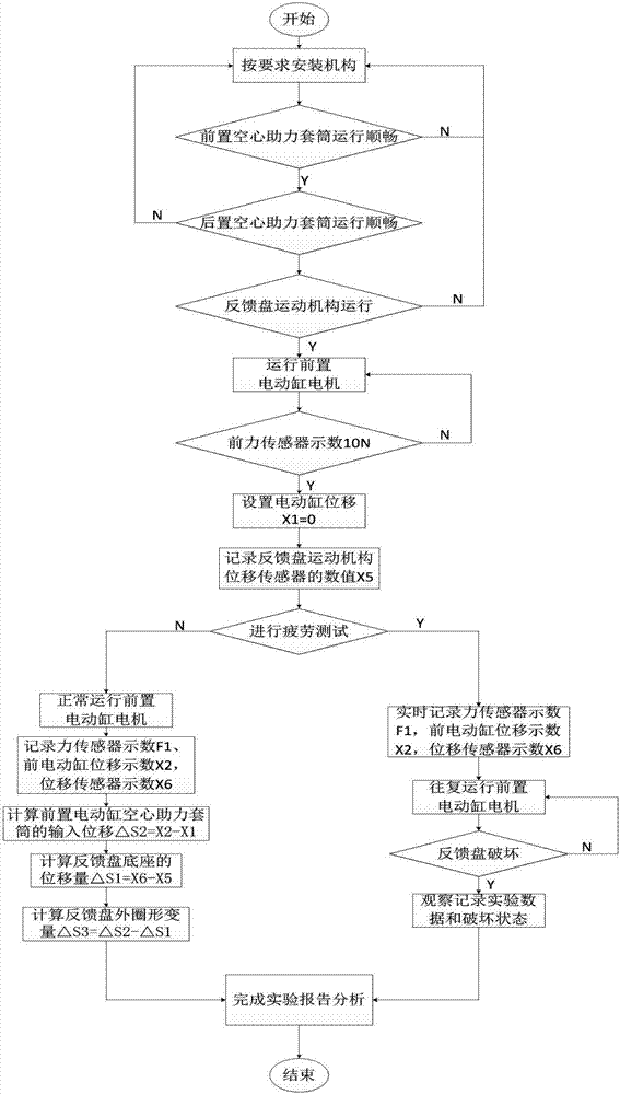
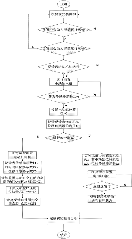
[0052] The embodiment of the present invention provides a simulated brake booster feedback disc operating condition test system. After the front and rear electric cylinders and the feedback disc movement mechanism are correctly installed, the connection of the electric cylinder is checked to ensure its smooth and reliable operation. At the same time, the feedback disc movement mechanism The overall central axis should be horizontally coincident with the axes of the front electric cylinder booster sleeve (7) and the rear electric cylinder booster sleeve (14), so as to ensure that the front and rear electric cylinder booster s...


PUM


Abstract

The invention belongs to the technical field of test equipment, and discloses a test system and a test method for simulating the working condition of a brake booster feedback disc. The dynamic working process of a feedback disc in practical work can be simulated precisely. Through acquisition, calculation and analysis of sensor information of encoder sensors of electric cylinders and force sensors and a displacement sensor separately configured on a mechanism, the force and deformation condition of a feedback disc can be reflected accurately, and error caused by artificial reading is avoided. Meanwhile, a return spring is set to simulate the return condition of the feedback disc, and can be used to test the fatigue failure characteristic of the feedback disc. The actual working states, including single pedal power input, single boosting input, and joint input of different boosting ratios, of a feedback disc can be simulated accurately using the electric cylinders according to the actual demand. The dynamic and static states of a feedback disc can be simulated accurately, and the fatigue characteristic can be analyzed in a more realistic manner.

Description

technical field [0001] The invention belongs to the field of brake booster test equipment, and in particular relates to a test system and a test method for simulating the working condition of a brake booster feedback disc. Background technique [0002] The brake booster can enable the driver to obtain greater vehicle braking force with a smaller pedal force, ensuring that the vehicle can quickly obtain the required braking force of different sizes during driving, and ensure the driving safety of the vehicle. At present, most of the brake boosters used in automobiles couple the driver's pedal force with the boost provided by the booster through the feedback disc, and quickly build pressure in the master cylinder and wheel cylinder to obtain the corresponding vehicle braking force. The feedback disc is the most critical link to establish the coupling force. During the formation of the coupling force, its inner ring and outer ring are respectively assisted by the pedal force an...

Claims


Application Information

Patent Timeline
IPC IPC(8): G01M13/00
CPCG01M13/00
Inventor 吴坚陈志成王宇马秀丹陈朋成赵健
Owner JILIN UNIV
Learn More