High-precision second neutron bunch switch

A high-precision, neutron beam technology, applied in the direction of material analysis using radiation diffraction, etc., can solve the problem of low repeat positioning accuracy, achieve the effect of fast and convenient opening and closing, short movement time, and high repeat positioning accuracy

Active Publication Date: 2017-08-18
DONGGUAN NEUTRON SCI CENT
View PDF2 Cites 10 Cited by
  • Summary
  • Abstract
  • Description
  • Claims
  • Application Information

AI Technical Summary

Problems solved by technology

[0004] In order to overcome the deficiencies in the prior art, the present invention aims to make breakthroughs and innovations in the prior art, and provide a neutron beamline switch, especially a neutron scatteri

Method used


Image

  • High-precision second neutron bunch switch
  • High-precision second neutron bunch switch
  • High-precision second neutron bunch switch

Examples


specific Embodiment approach

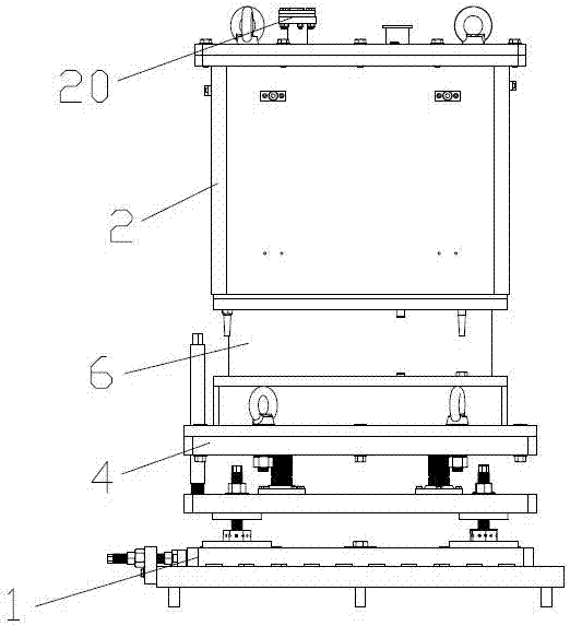
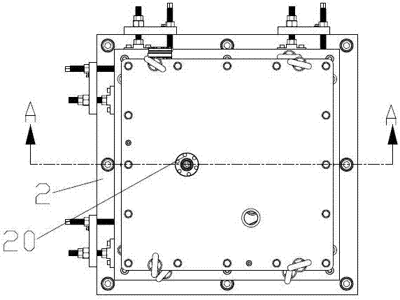
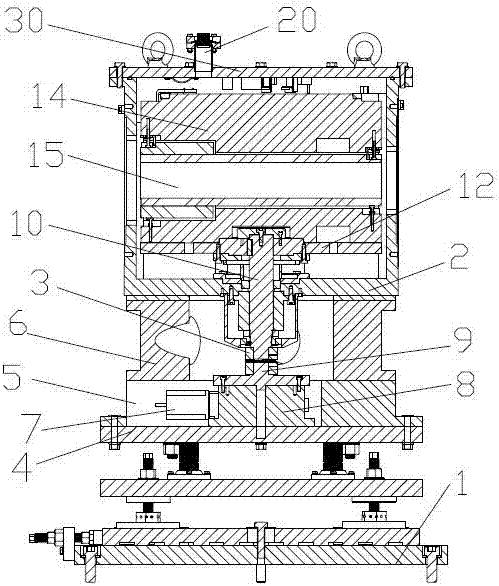
[0035] Such as Figure 1-11 As shown, a high-precision second neutron beam switch, the switch mainly includes a base 1 installed from bottom to top, a rotating system, a transmission system, a vacuum shell system, a rotary table system and a control system; wherein The rotation system is installed on the base 1, the transmission system is connected to the rotation system coaxially through the coupling 3, and the rotary table system is connected to the transmission system by coaxial rotation. The vacuum housing system has a vacuum housing 2, a housing 2 The upper surface is provided with lifting rings to facilitate hoisting and maintenance. The upper part of the transmission system and the rotating round table system are installed in the vacuum housing 2, and the control system is electrically connected to the rotating system. The structure of the vacuum housing 2 of the vacuum housing system and The vacuum method adopts the structure disclosed in the patent No. 201310399825.0 ...

Embodiment

[0042] Embodiment: Assume that the present invention is in an initial state, that is, the neutron conduit 15 is in a conduction state.

[0043] Such as Figure 13 As shown, when the neutron beam is closed, the motor 7 drives the high-precision turntable to rotate to generate torque, which is transmitted to the rotating disk through the rotating shaft 9, the coupling 3, and the transmission shaft 10, because the rotating disk 14 and the connecting disk 12 The system is fixed together by the fixed rod 13 and the screw, and then drives the rotating round table 14 to drive the neutron tube 15 inside to rotate. When the rotation reaches the 90° position, the second limit switch triggers the stopper 19 to trigger the third limit switch 23 And the fourth limit switch 24, the rotation stops, and the boron carbide block 16 is facing the neutron beam.

[0044] Such as Figure 12 As shown, when the neutron beam is turned on, the motor 7 reversely drives the high-precision turntable to ...


PUM


Abstract

The invention relates to the technical field of a neutron bunch switch, and particularly relates to a high-precision second neutron bunch switch applied to a neutron scattering spectrometer for realizing the switching of turning on and off the neutron bunch switch; through an operation system starting switch, a rotating system drives a transmission system to rotate, and a driving shaft of the transmission system transmits torque to a rotating circular cone system; a rotating circular cone and a neutron guide pipe at the inner part are rotated together at 90 degrees, thus a boron carbide baffle intercepts a neutron bunch flow; the rotating circular cone is reversely rotated at 90 degrees so that the neutron guide pipe is conducted; through the reciprocating motion at 90 degrees, the switching of opening and closing the neutron guide pipe is realized. The parts are rigidly connected and coaxially treated by a step or a pin structure; the parts apply driving of a motor, feedback control of an encoder, and minor control of a limiting switch; an optical grid ruler can feedback and position a terminal position; the high-precision second neutron bunch switch is simple in operation, short in movement time, high in repeat positioning precision in a conducting state, and capable of rapidly and conveniently opening and closing the neutron guide pipe.

Description

technical field [0001] The invention relates to the technical field of a neutron beamline switch, in particular to a high-precision second neutron beamline switch applied to a neutron scattering spectrometer for switching between neutron beamline on and off . Background technique [0002] Neutron spectrometers are mainly used to study the structure and properties of various substances. At present, the neutron spectrometers built in various countries in the world can be divided into two categories. One is called neutron spallation source spectrometer. The neutron spallation source is Neutrons are produced based on accelerator-accelerated proton bombardment targets; the other type is called neutron reactor spectrometers, and neutron reactors are based on uranium fission to produce neutrons. The neutron beamline switch is used in the neutron spectrometer to open and cut off the neutron beam. In the on state, the neutron beam is transmitted to the sample through the neutron opt...

Claims


Application Information

Patent Timeline
IPC IPC(8): G01N23/20
Inventor 吴延岩孙远肖松文朱涛
Owner DONGGUAN NEUTRON SCI CENT
Why Eureka
Try Eureka