Supercharge Your Innovation With Domain-Expert AI Agents!

Touch control module window hidden type clinging structure

A touch module and hidden technology, applied in the fields of instruments, computing, electrical and digital data processing, etc., can solve the problems of large visual contrast between the touch window and the panel ink area, affecting the visual effect of the touch panel, and shortage of supply resources, etc. , to meet the differentiated needs of customers, compact structure, low scrap rate

Pending Publication Date: 2017-08-18
MULTEK DISPLAY
View PDF3 Cites 4 Cited by
  • Summary
  • Abstract
  • Description
  • Claims
  • Application Information

AI Technical Summary

Problems solved by technology

However, in the existing bonding technology, when the display panel is not lit, the visual contrast between the touch window and the ink area of ​​the panel is relatively large, the boundary between the window and the ink area is clear, and even the graphics or metal bridge points of the rear sensor can be seen. Affect the overall visual effect of the touch panel
[0003] At present, the method of achieving the integrated black effect of the touch screen cover is generally achieved by using glass or plastic materials with neutral gray light reduction effects, or coating a semi-reflective and semi-permeable film on the cover by vacuum sputtering. The one-piece black effect of the cover plate made of the cover material with medium gray light reduction effect is better, but there are problems of high material price and shortage of supply resources; the one-piece black of the vacuum sputtering coating method cannot achieve a real black background, and will appear A bright white specular reflection effect, in most cases, cannot meet people's requirements for a one-piece black effect, and there is also a problem of high price

Method used


Image

  • Touch control module window hidden type clinging structure
  • Touch control module window hidden type clinging structure
  • Touch control module window hidden type clinging structure

Examples


Embodiment Construction

[0016] The technical solution of this patent will be further described in detail below in conjunction with specific embodiments.

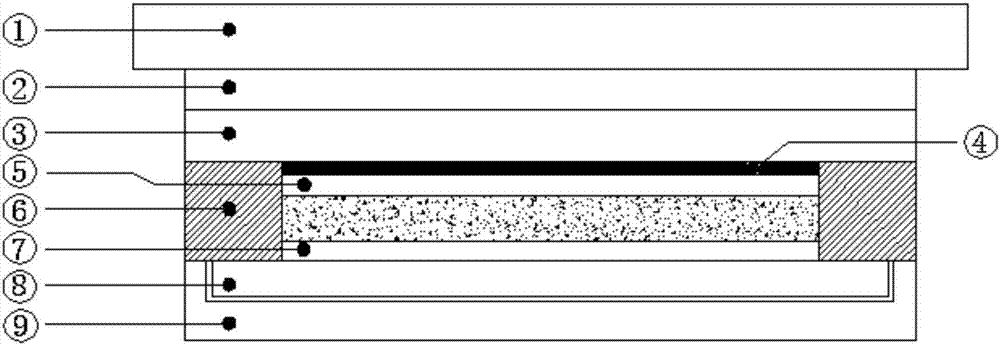
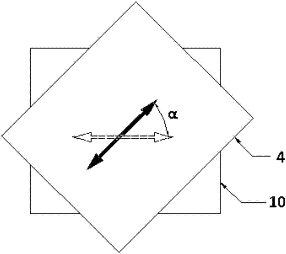
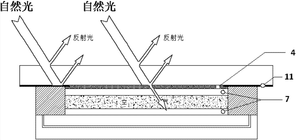
[0017] see Figure 1-4 , a touch module window hidden bonding structure, including touch screen glass cover plate 1, transparent optical adhesive 2, touch screen functional sheet 3, polarizer 4, ultra-low reflection film A5, ultra-low Reflective film B7, LCD 8 and backlight plate 9; the upper end of the polarizer 4 is attached to the lower end of the touch screen functional sheet 3, the lower end of the polarizer 4 is attached to the upper end of the ultra-low reflection film A5, and the touch screen includes a touch screen glass cover plate 1, transparent optical glue 2 and The touch screen functional sheet 3, the touch screen glass cover 1 and the touch screen functional sheet 3 are connected through transparent optical glue 2; there is a gap between the ultra-low reflection film A5 and the ultra-low reflection film B7, and the lower end of the u...


PUM


Abstract

The invention discloses a touch control module window hidden type clinging structure which comprises a touch screen glass cover plate, a transparent optical adhesive, a touch screen function sheet, a polaroid, an ultralow reflection membrane A, an ultralow reflection membrane B, an LCD (Liquid Crystal Display) and a backlight plate which are overlapped in sequence from top to bottom, wherein a touch screen comprises the touch screen glass cover plate, the transparent optical adhesive and the touch screen function sheet; the touch screen glass cover plate is connected with the touch screen function sheet through the transparent optical adhesive; the touch screen, the LCD and the backlight plate are connected through a foam adhesive; an included angle of 45 degrees is formed between the polaroid and the polaroid on the LCD. The touch control module window hidden type clinging structure is reasonable in structural design, compact in structure, relatively low in cost, high in clinging yield, simple in clinging process, small in equipment investment, simple in rework and low in rejection rate and can be very well applied to vehicle-mounted devices, medicinal instruments and industrial control products, a complete clinging effect is achieved, the clinging cost can be very well controlled, an integral dark display effect is achieved, and different requirements of customers can be met.

Description

technical field [0001] The invention relates to the technical field of touch display modules, in particular to a hidden bonding structure of a touch module window. Background technique [0002] At present, there are two types of bonding technologies commonly used for touch modules and display modules: full bonding and frame bonding. Full bonding uses optical glue or water glue to seamlessly bond the touch screen and display panel on the entire surface of the window area. Frame bonding is The touch screen and the display panel are bonded with frame glue, and the frame glue is hidden in the ink area of ​​the touch screen, while the touch screen and the display panel are separated by a gap of the thickness of the frame glue. However, in the existing bonding technology, when the display panel is not lit, the visual contrast between the touch window and the ink area of ​​the panel is relatively large, the boundary between the window and the ink area is clear, and even the graphic...

Claims


Application Information

Patent Timeline
Patent Type & Authority Applications(China)
IPC IPC(8): G02F1/1333G06F3/041
CPCG02F1/13338G06F3/041G06F2203/04103
Inventor 王善于乐成龙赵润成
Owner MULTEK DISPLAY
Features
  • R&D
  • Intellectual Property
  • Life Sciences
  • Materials
  • Tech Scout
  • Unparalleled Data Quality
  • Higher Quality Content
  • 60% Fewer Hallucinations
Learn More