Integrated box-packaged FD metal oxide varistors (FDMOV) composite assembly with air discharging structure
An air discharge, composite component technology, applied in the direction of varistor core, resistor shell/packaging shell/potting, varistor, etc., can solve the problem that conventional MOV cannot meet the actual needs, and achieve large economical use Value, no leakage current, low cost effect
- Summary
- Abstract
- Description
- Claims
- Application Information
AI Technical Summary
Problems solved by technology
Method used
Image
Examples
Embodiment 1
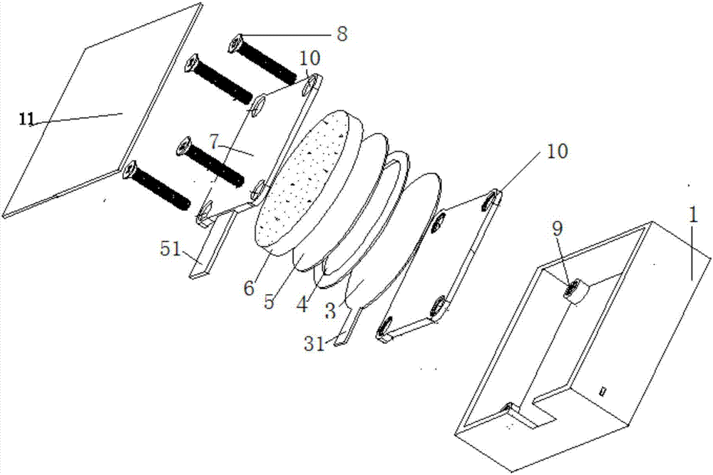
[0031] Such as figure 1 with figure 2 As shown, this embodiment provides a box-packed FDMOV composite assembly, including a box body 1, an insulating fixing plate 2, an upper discharge electrode 3, an insulating ring piece 4, a lower discharge electrode 5, an MOV chip 6, a lead-out electrode piece 7 and screws 8.
[0032] Four corners of the bottom of the box body 1 are provided with four screw holes 9, and the insulating fixing plate 2 is rectangular, and four through holes 10 are arranged at the four corners.
[0033] The upper discharge electrode 3 is circular and is provided with an upper discharge electrode lead-out pin 31 .
[0034] The insulating ring sheet 4 is annular, and its shape is directly larger than the diameter of the MOV chip 6 by 1-5mm.
[0035] The lower discharge electrode 5 is circular.
[0036] The MOV chip 6 is coated with compound electrodes on the surface.
[0037] The lead-out electrode sheet 7 is a metal rectangle, with through holes 10 provid...
Embodiment 2
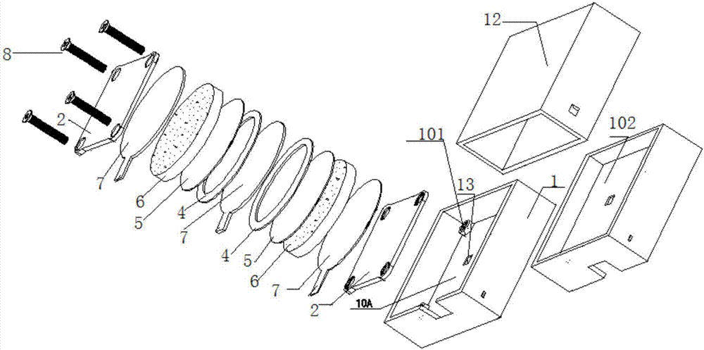
[0046] Such as Figure 2a As shown, the difference between this embodiment and Embodiment 1 is that a single double-layer box body 1 is adopted, an insulating fixing plate 2 is added, a lead-out electrode sheet 7, an MOV chip 6, a lower discharge electrode 5 and an insulating ring sheet 4 are added. Form two series circuits.
[0047] According to the insulating fixed plate 2, lead-out electrode piece 7, MOV chip 6, lower discharge electrode 5, insulating ring piece 4, upper discharge electrode 3, insulating ring piece 4, lower discharge electrode 5, MOV chip 6, lead-out electrode piece 7, insulation The fixing plates 2 are stacked sequentially, put into the first space 101 in the box body 1, 4 screws pass through the insulating fixing plate 2, the 4 through holes 10 on the insulating fixing plate 2 are fastened to the screws in the box body 110 Hole 9, after installation, potting silica gel, epoxy resin, put on box body 1 shell 12.
[0048] In this embodiment, the box body 1...
Embodiment 3
[0055] Such as Figure 3a with 3bAs shown, the present embodiment is a three-group series structure assembled together, which can conveniently form an angular application circuit.
[0056] The difference between this embodiment and embodiment 1 is that the 3 groups formed according to embodiment 1 are connected in series.
[0057] Such as Figure 3a As shown, one group consists of upper discharge electrode 3, insulating ring 4, MOV chip 6, and lead-out electrode 7, and another group consists of upper discharge electrode 3, insulating ring 4, MOV chip 6, and 5 lead-out electrodes. The third group is composed of the upper discharge electrode sheet 3, the insulating ring sheet 4, the MOV chip 6, and the lead electrode sheet 7. The three groups are placed in sequence, and the uppermost and the lowermost are provided with insulating fixing plates 2 and 1, and the whole is put into the box. 1. Fasten according to the above embodiment. After installation, potting silica gel, epox...
PUM
 Abstract
Description
Claims
Application Information
 - R&D Engineer
- R&D Manager
- IP Professional
- Industry Leading Data Capabilities
- Powerful AI technology
- Patent DNA Extraction
Browse by: Latest US Patents, China's latest patents, Technical Efficacy Thesaurus, Application Domain, Technology Topic, Popular Technical Reports.
© 2024 PatSnap. All rights reserved.Legal|Privacy policy|Modern Slavery Act Transparency Statement|Sitemap|About US| Contact US: help@patsnap.com


