Arrangement for overload protection for overvoltage protection equipment

An overload protection and protection device technology, applied in emergency protection circuit devices, overvoltage protection resistors, emergency protection circuit devices for limiting overcurrent/overvoltage, etc. The whole range of leakage current to average short-circuit current, cost-intensive design, etc.

Active Publication Date: 2018-12-21
デーンエスエープルスツェオーカーゲー
View PDF7 Cites 0 Cited by
  • Summary
  • Abstract
  • Description
  • Claims
  • Application Information

AI Technical Summary

Problems solved by technology

[0007] Such a mechanism has the disadvantage in fault or overload situations that it cannot reliably cover the entire range from relatively large leakage currents to the average short-circuit current
[0008] Alternative circuit designs for intrinsically safe surge arresters, such as the combination of a surge ar

Method used


Image

  • Arrangement for overload protection for overvoltage protection equipment
  • Arrangement for overload protection for overvoltage protection equipment

Examples


Embodiment Construction

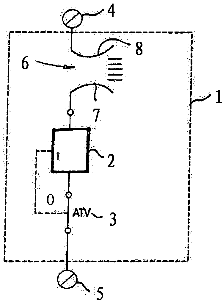
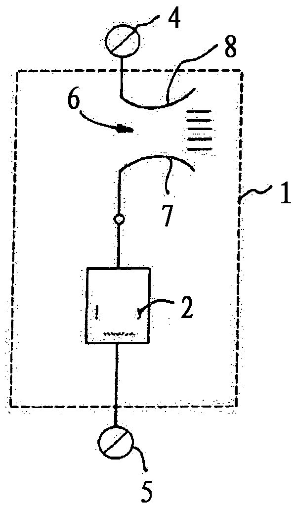
[0031] In the drawing, the description begins first with structural unit 1 . The structural unit 1 is characterized by a common housing which has a type II surge arrester 2 inside it.

[0032] Type II surge arrester 2 in accordance with figure 1 In the case of an embodiment of the present invention, there is a thermal separation device 3 known per se which responds in the event of an overload.

[0033] The structural unit 1 also has external connections 4 and 5 .

[0034] Internally, the switching unit 6 is connected in series with the type II surge arrester 2 .

[0035] The switching unit has two non-movable fixed contacts 7; 8.

[0036] The contacts 7 ; 8 are positioned at a narrow distance and can be part of the connections of the surge arrester 2 .

[0037] The spacing is selected such that during each surge current or discharge process the switching device 6 is brought into the quasi-closed state due to the arc formed.

[0038] In contrast, in the standstill state, t...


PUM


Abstract

The invention relates to an arrangement for overload protection for overvoltage protection equipment, consisting of at least one type II overvoltage arrester with or without a thermal disconnecting device that responds in the case of overload. According to the invention, a switching unit free of movable contacts is connected in series with the at least one overvoltage arrester and structurally combined therewith, which switching unit has at least two stationary switching contacts located at a small distance, wherein the distance of the switching contacts is specified in such a way that, in thecase of every surge current event or arresting event, the switching device goes into a quasi closed state because of the arc formed; in contrast, in the idle state the voltage of the connected network drops at the switching device, whereby the overvoltage arrester lying in series remains free of leakage current.

Description

technical field [0001] The invention relates to a system for overload protection overvoltage protective devices according to claim 1, the system comprising at least one surge arrester with or without response in the overload situation thermal separation device. Background technique [0002] A system for overload protection of overvoltage protective devices is known from DE 10 2013 019 391 A1. [0003] The system has at least one voltage limiting element and at least one voltage switching element. A fuse is optionally present. The voltage-limiting element is designed as a varistor and the voltage-switching element is designed as a spark gap, the aforementioned elements being connected in series. Furthermore, in order to prevent impermissible pulse currents, the monitoring spark gap is connected in parallel to the voltage limiting element in the series circuit in a bypass manner. In addition, a thermal monitoring device may be provided which bridges not only the monitoring...

Claims


Application Information

Patent Timeline
IPC IPC(8): H01T1/14H01T1/16H01T2/02H01T4/10H01T4/14H01C7/12H02H9/06
CPCH01T1/14H01T1/16H01T2/02H01T4/10H01T4/14H01C7/126H01C7/12H02H9/06H02H7/008H02H9/008
Inventor R·布罗克
Owner デーンエスエープルスツェオーカーゲー
Why Eureka
Try Eureka