High voltage cabinet integrated installation device

A technology for installation devices and high-voltage cabinets, which is applied in the direction of switchgear and electrical components, which can solve problems such as difficulty in installing high-voltage cabinet equipment in place, inability to install hoisting and driving, and equipment damage, so as to solve the problem of mechanical damage to the cabinet body and improve The effect of operation method and convenient loading and unloading

Active Publication Date: 2019-10-22
STATE GRID JIANGSU ELECTRIC POWER CO WUXI POWER SUPPLY CO +1
View PDF5 Cites 0 Cited by
  • Summary
  • Abstract
  • Description
  • Claims
  • Application Information

AI Technical Summary

Problems solved by technology

Because the indoor space of the high-voltage cabinet is small, most of them cannot be installed for hoisting and driving, and the high-voltage cabinet equipment is relatively large in size and heavy in weight, which brings great difficulties to the in-place installation of the high-voltage cabinet equipment.
The previous installation method is to use multi-person cooperation, place steel pipes under the cabinet, and use tools such as crowbars to realize the installation of high-voltage cabinet equipment. During the installation process, it is not only time-consuming and labor-intensive, but sometimes there may be problems caused by improper use of crowbars. Cause equipment damage, there is also a certain danger during installation

Method used


Image

  • High voltage cabinet integrated installation device
  • High voltage cabinet integrated installation device
  • High voltage cabinet integrated installation device

Examples


Embodiment Construction

[0021] The present invention will be further described below in conjunction with specific drawings and embodiments.

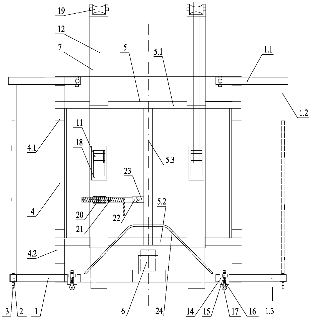
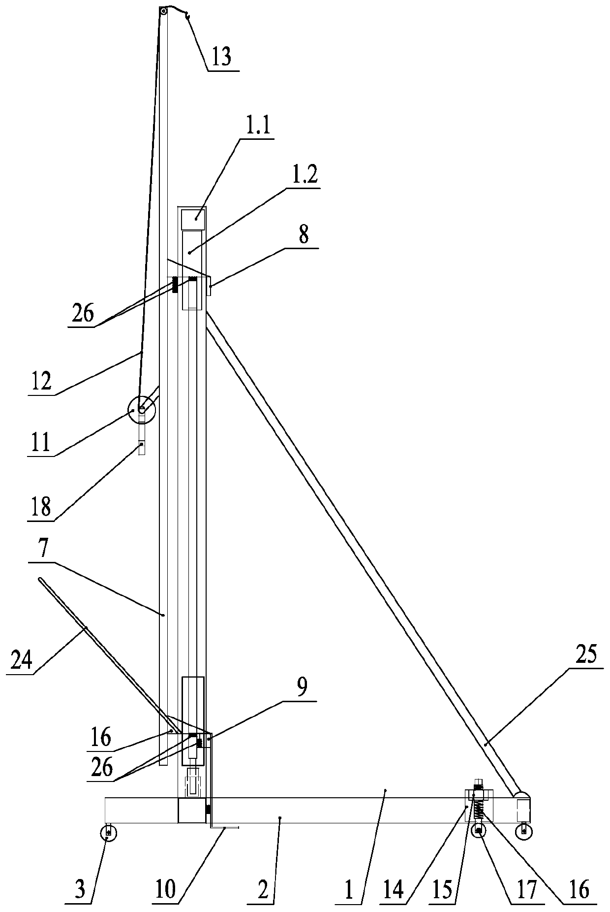
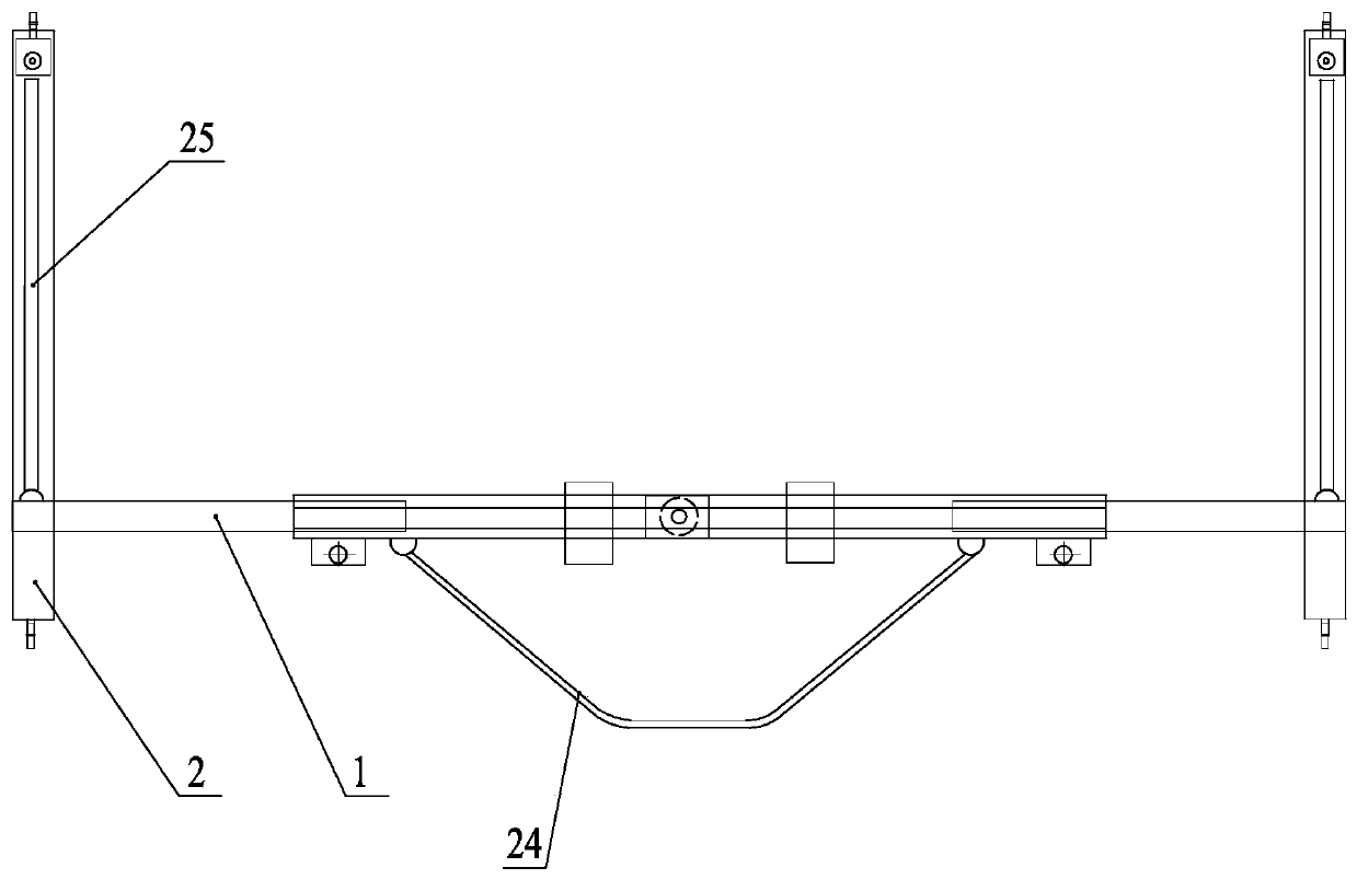
[0022] As shown in the figure: the integrated installation device for the high-voltage cabinet in the embodiment is mainly composed of a rectangular frame 1, a longitudinal support beam 2, a walking caster 3, a vertical guide rod 4, an I-shaped lifting frame 5, a jack 6 and a movable rod 7; The rectangular frame 1 is erected, and a longitudinal support beam 2 perpendicular to the plane of the rectangular frame 1 is fixedly connected at two lower corners of the rectangular frame 1, and walking casters 3 are installed at the front and rear ends of the longitudinal support beam 2 respectively. Two vertical guide rods 4, one on the left and one right, are arranged in the rectangular frame 1. The upper and lower ends of the vertical guide rod 4 are respectively fixedly connected with the upper frame 1.1 and the lower frame 1.3 of the rectangular frame 1, and the upper p...


PUM


Abstract

The invention relates to a high-voltage cabinet integrated mounting device. Longitudinal support beams are separately fixed and connected to two lower corners of a rectangular frame, and casters are mounted at the front and rear ends of the longitudinal support beam; two vertical guide rods are arranged in the rectangular frame at the left side and the right side thereof; the upper and lower ends of the vertical guide rod are separately fixedly connected to an upper peripheral frame and a lower peripheral frame of the rectangular frame; an upper vertical guide sliding chute and a lower vertical guide sliding chute are respectively arranged in an upper part and a lower part of the vertical guide rod, an I-shaped lifting frame is arranged between the two vertical guide rods and can move freely; a jack is mounted on the lower peripheral frame, and the end of a piston rod of the jack is upwards connected with the I-shaped lifting frame; two movable rods are hung on the I-shaped lifting frame through upper and lower hooks, and the lower end of the movable rod is provided with a plain shovel; a winding pulley is provided at the rear side of the movable rod, and a safety belt is wound on the winding pulley and the other end of the safety belt is connected with a lifting hook. The high-voltage cabinet integrated mounting device is suitable for different cabinet foundations, convenient in handling, and can greatly improve the construction quality and efficiency.

Description

Technical field [0001] The invention relates to an integrated installation device for a high-voltage cabinet, which belongs to the technical field of electric equipment installation. Background technique [0002] In the process of substation renovation and expansion, new construction, the installation of high-voltage cabinet equipment is a key point, but the fast and accurate installation of high-voltage cabinet equipment is a difficult point. Because the indoor space of the high-voltage cabinet is small, most of them cannot be installed with hoisting cranes, and the equipment of the high-voltage cabinet is relatively large and heavy, which brings great difficulties to the installation of the high-voltage cabinet equipment. The previous installation method used multi-person cooperation, placing steel pipes under the cabinet, and using tools such as crowbars to implement the installation of high-voltage cabinet equipment. During the installation process, it was time-consuming and ...

Claims


Application Information

Patent Timeline
Patent Type & Authority Patents(China)
IPC IPC(8): H02B3/00
Inventor 韩刚顾云陶臻郑云汪海
Owner STATE GRID JIANGSU ELECTRIC POWER CO WUXI POWER SUPPLY CO
Why Eureka
Try Eureka