Rotor unmanned aerial vehicle power line inspection system

A technology of unmanned rotor and electromechanical power, applied in the direction of overhead lines/cable equipment, etc., can solve the problems of heavy workload, high risk of manual line inspection, high labor intensity, etc., achieve low requirements, improve line inspection efficiency, and The effect of fast line speed

Inactive Publication Date: 2017-08-18
广州全成多维信息技术有限公司
View PDF4 Cites 11 Cited by
  • Summary
  • Abstract
  • Description
  • Claims
  • Application Information

AI Technical Summary

Problems solved by technology

At present, the iron tower line inspection is mainly carried out by manual climbing. With the rapid expansion of power lines, the workload of line inspection is also increasing. The traditional line inspection method has the disadvantages of high labor intensity, difficult working conditions, and low efficiency. Therefore, there is an urgent need for a more advanced, scientific, efficient and highly automated line inspection method to meet and adapt to the needs of the construction and development of modern power networks. Traditional methods often encounter the following problems. 1. Manual inspection The line is faced with the disadvantages of high risk, heavy workload and slow speed; 2. During natural disasters such as ice and snow disasters, earthquakes, landslides, etc., the line patrol personnel cannot reach the line inspection site, and the line patrol work cannot be carried out; 3. The line personnel are in the Line patrols in mountainous areas, water areas and other areas have high risks, and the complex geographical environment has caused danger to the lives of line patrol personnel; in summary, in order to solve the above technical problems, a new technical solution is proposed

Method used


Image

  • Rotor unmanned aerial vehicle power line inspection system
  • Rotor unmanned aerial vehicle power line inspection system

Examples


specific Embodiment approach

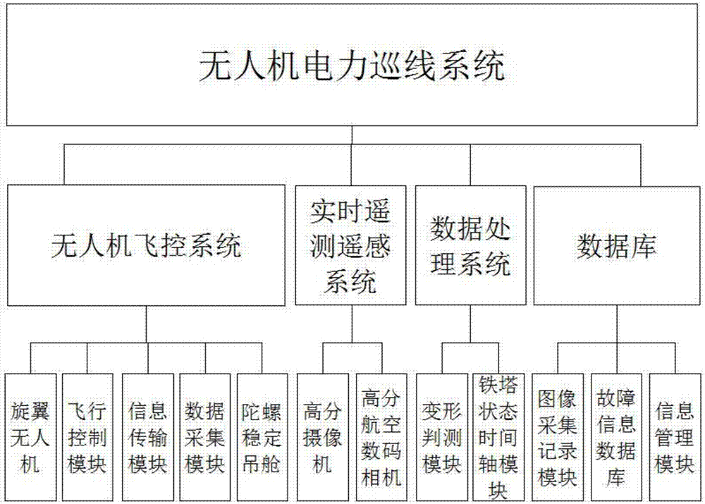
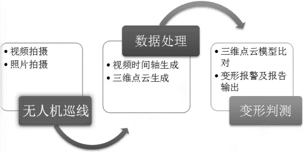
[0023] The specific implementation is as follows: the combination of the real-time telemetry and remote sensing system and the data processing system can achieve close-range stereo image matching and data collection management. The close-range stereo image matching is based on the base distance between cameras of the airborne stereo photography system, based on grayscale projection and The epicenter-constrained stereoscopic image matching algorithm realizes the rapid automatic matching of the same-named image points in the airborne stereoscopic image; for the CCD stereoscopic photography system in the airborne system, using the relatively mature spatial data acquisition system for GIS applications, the system Based on the AO component, the stereoscopic measurement embedded in the airborne CCD image realizes the integrated organization, management and data processing of GPS, INS, CCD image and basic geographic data, and directly collects, edits and processes vector geographic inf...


PUM


Abstract

The invention relates to a rotor unmanned aerial vehicle power line inspection system and belongs to the power tower inspection equipment and facility field. The system comprises an unmanned aerial vehicle flight control system, a real-time telemetry and remote sensing system, a data processing system and a database; the unmanned aerial vehicle flight control system comprises a rotor unmanned aerial vehicle, a flight control module arranged in the rotor unmanned aerial vehicle, an information transmission module arranged in the rotor unmanned aerial vehicle, a data acquisition module arranged in the rotor unmanned aerial vehicle and a gyroscope stabilization pod located on the rotor unmanned aerial vehicle; the real-time telemetry and remote sensing system comprises a high-definition camera mounted on the rotor unmanned aerial vehicle and a high-definition aerial digital camera mounted on the rotor unmanned aerial vehicle; and the data processing system comprises a deformation judgment module and a tower state time axis module. Since the unmanned aerial vehicle just has low requirements for take-off and landing environments, so that the rotor unmanned aerial vehicle power line inspection system can be applied to mountainous line inspection. Compared with manned helicopter line inspection, the rotor unmanned aerial vehicle power line inspection system can improve the safety of operators and reduce costs.

Description

[0001] Technical field: [0002] The invention relates to electric power tower detection equipment and facilities, in particular to a power line inspection system for a rotor unmanned aerial vehicle. [0003] Background technique: [0004] With the rapid development of the electric power industry, all kinds of electric power towers are blooming everywhere in our country at present, and their distribution is scattered, and many iron towers are arranged in mountainous areas and on the top of buildings. How to quickly inspect these iron towers to ensure smooth power transmission has become a difficult problem . At present, the iron tower line inspection is mainly carried out by manual climbing. With the rapid expansion of power lines, the workload of line inspection is also increasing. The traditional line inspection method has the disadvantages of high labor intensity, difficult working conditions, and low efficiency. Therefore, there is an urgent need for a more advanced, scien...

Claims


Application Information

Patent Timeline
Patent Type & Authority Applications(China)
IPC IPC(8): H02G1/02
CPCH02G1/02
Inventor 孙照辉陈顺生李高潮解玉林庞国俊毛万里宋小波田娜王瑞亮
Owner 广州全成多维信息技术有限公司
Why Eureka
Try Eureka