Heat shield element and method for the production thereof
A heat shielding and component technology, applied in the field of heat shielding components, can solve the problem that the edge area of the heat shielding component cannot be sufficiently cooled by the cooling air channel, and achieve the effects of reducing the amount of cooling air, abandoning impact cooling, and reducing emissions
- Summary
- Abstract
- Description
- Claims
- Application Information
AI Technical Summary
Problems solved by technology
Method used
Image

Examples
Embodiment Construction
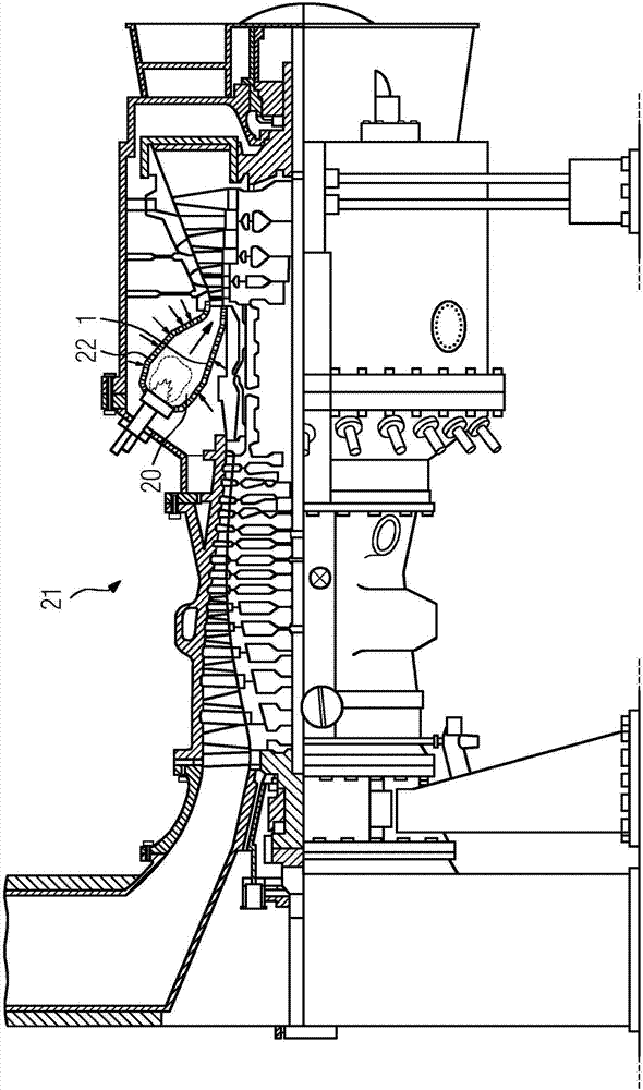
[0035] figure 1 Shown is a gas turbine 21 which is partially shown in longitudinal section. The gas turbine 21 has a compressor, an annular combustor 20 with a plurality of burners for fuel in liquid or gaseous form, and for driving the compressor and figure 1 The generator turbine is not shown. Here, the combustion chamber wall is covered with the heat shielding element 1 , or the heat shielding element 1 is mounted on a support structure 22 on the combustion chamber wall. During operation of the gas turbine 21, air is drawn in from the environment. In the compressor, the air is compressed and thus partly heated. A small part of the air is taken from the compressor and passed into the heat shield element 1 as a cooling medium, the majority of the air is sent to the burner for combustion. In the combustor 20, this majority of the air from the compressor is combined with fuel in liquid or gaseous form and combusted. The hot gases that drive the gas turbine 21 are generated...
PUM
 Abstract
Description
Claims
Application Information
 - R&D
- Intellectual Property
- Life Sciences
- Materials
- Tech Scout
- Unparalleled Data Quality
- Higher Quality Content
- 60% Fewer Hallucinations
Browse by: Latest US Patents, China's latest patents, Technical Efficacy Thesaurus, Application Domain, Technology Topic, Popular Technical Reports.
© 2025 PatSnap. All rights reserved.Legal|Privacy policy|Modern Slavery Act Transparency Statement|Sitemap|About US| Contact US: help@patsnap.com