Coil component

A coil component and coil technology, which is applied in coil manufacturing, transformer/inductor parts, electrical components, etc., can solve the problems of reducing the number of turns of coil electrodes 102 and limited space, and achieve the effect of improving heat dissipation characteristics

Active Publication Date: 2017-08-18
MURATA MFG CO LTD
View PDF7 Cites 2 Cited by
  • Summary
  • Abstract
  • Description
  • Claims
  • Application Information

AI Technical Summary

Problems solved by technology

However, when the winding axis forms a circular toroidal coil, the space inside the circle is limited, so if the diameter of the inner columnar conductor 102c is increased, the number of turns of the coil electrode 102 will decrease.

Method used


Image

  • Coil component
  • Coil component
  • Coil component

Examples


no. 1 approach >

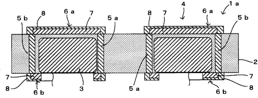
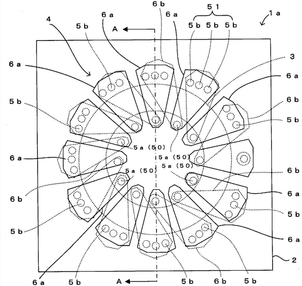
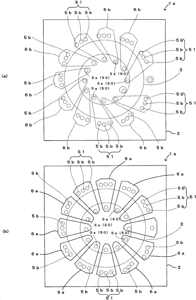
[0030] refer to Figure 1 ~ Figure 3 The coil component 1a according to the first embodiment of the present invention will be described. in, figure 1 is a sectional view of the coil component 1a, figure 2 is a plan view of the coil component 1a, image 3 It is a figure for demonstrating wiring pattern 6a, 6b. in addition, image 3 (a) is a plan view of the coil component 1a in a state where the upper wiring pattern 6a is removed, image 3 (b) is a plan view of the coil component 1a in a state where the lower wiring pattern 6b is removed. also, figure 1 Yes figure 2 A cross-sectional view in the direction of the arrow A-A. In addition, in image 3 In (a), the wiring for input and output connected to the end part of the coil electrode 4 is abbreviate|omitted.

[0031] like Figure 1 ~ Figure 3 As shown, the coil component 1a according to this embodiment includes an insulating layer 2 in which a coil core 3 is embedded, and a coil electrode 4 wound around the coil ...

no. 2 approach >

[0058] refer to Figure 4 The coil component 1b according to the second embodiment of the present invention will be described. In addition, this figure is a plan view of the coil component 1b in a state in which the lower wiring pattern 6b is removed, and is the same as image 3 (b) Corresponding figure.

[0059] like Figure 4 As shown, the coil component 1b related to this embodiment is the same as the reference Figure 1 ~ Figure 3 The coil component 1a of the first embodiment described is different in that the number of outer metal pins 5b constituting each outer conductor 51 is different, and the outer metal pins 5b are formed to be smaller than the inner metal pins 5a (excluding the metal pins for external connection). outside) rough. The other configurations are the same as those of the coil component 1a of the first embodiment, so the same reference numerals are assigned and descriptions thereof are omitted.

[0060] In this case, each outer conductor 51 is compos...

no. 3 approach >

[0063] refer to Figure 5A coil component 1c according to a third embodiment of the present invention will be described. In addition, this figure shows the plan view of the coil component 1c in the state which removed the lower wiring pattern 6b, and is the same as image 3 (b) Corresponding figure.

[0064] like Figure 5 As shown, the coil component 1c related to this embodiment is the same as the reference Figure 1 ~ Figure 3 The coil component 1a of the first embodiment described is different in that each inner metal needle 5a is formed thicker than each outer metal needle 5b. The other configurations are the same as those of the coil component 1a of the first embodiment, so the same reference numerals are assigned and descriptions thereof are omitted.

[0065] In this case, each outer metal needle 5b is formed with the same thickness and length, and each inner metal needle 5a is also formed with the same thickness and length. Also, each inner metal needle 5a is form...


PUM


Abstract

The purpose of the present invention is to facilitate decrease in the resistance and improvement in the heat dissipation characteristics of a coil electrode in a coil component provided with: an insulating layer having an annular coil core buried therein; and the coil electrode wound on the coil core. A coil electrode 4 of a coil component 1a has: a plurality of lower wiring patterns 6b arranged on the lower surface of an insulating layer 2; a plurality of upper wiring patterns 6a arranged on the upper surface of the insulating layer 2 so as to make a plurality of pairs with the respective lower wiring patterns 6b; a plurality of inner conductors 50 arranged at the inner peripheral side of a coil core 3 and each connecting one end of a corresponding one of the lower wiring patterns 6b to one end of the upper wiring pattern 6a that is paired with this lower wiring pattern 6b; and a plurality of outer conductors 51 arranged at the outer peripheral side of the coil core 3 and each connecting the other end of a corresponding one of the lower wiring patterns 6b to the other end of the upper wiring pattern 6a that is adjacent to the upper wiring pattern 6a that is paired with this lower wiring pattern 6b. Each outer conductor 51 is formed such that the volume of the outer conductor 51 is larger than the volume of each inner conductor 50.

Description

technical field [0001] The present invention relates to a coil component including an insulating layer in which a coil core is embedded, and a coil electrode wound around the coil core. Background technique [0002] In electronic devices using high-frequency signals, coil components are sometimes used to prevent noise. Such a coil component is composed of a coil core formed of a magnetic material or the like, and a coil electrode wound around the coil core. Here, the winding of the coil electrodes is often performed manually, and eliminating this manual operation becomes a problem in achieving reduction of the manufacturing cost of the coil component. [0003] Therefore, coil components that do not require manual winding work have been proposed conventionally. E.g, Figure 9 The coil component 100 described in the illustrated Patent Document 1 is a laminated coil component including a magnetic layer 101 formed by laminating a plurality of magnetic sheets and a coil electro...

Claims


Application Information

Patent Timeline
Patent Type & Authority Applications(China)
IPC IPC(8): H01F17/06H01F17/00H01F27/28H01F41/04H01F41/08
CPCH01F17/06H01F41/08H01F17/0013H01F41/043H01F27/2804H01F27/323
Inventor 大坪喜人黑部淳司西出充良
Owner MURATA MFG CO LTD
Why Eureka
Try Eureka