Control device for direct power converter

A technology of power converters and control devices, applied in high-efficiency power electronic conversion, output power conversion devices, control/regulation systems, etc., can solve problems such as reactor current discontinuity

Active Publication Date: 2017-08-18
DAIKIN IND LTD
View PDF5 Cites 1 Cited by
  • Summary
  • Abstract
  • Description
  • Claims
  • Application Information

AI Technical Summary

Problems solved by technology

[0005] Non-Patent Document 2 shows a case where the reactor current flowing through the reactor i

Method used


Image

  • Control device for direct power converter
  • Control device for direct power converter
  • Control device for direct power converter

Examples


no. 1 Embodiment approach

[0150] The operation of the first embodiment and the direct type power converter introduced in Patent Document 2 will be described in comparison.

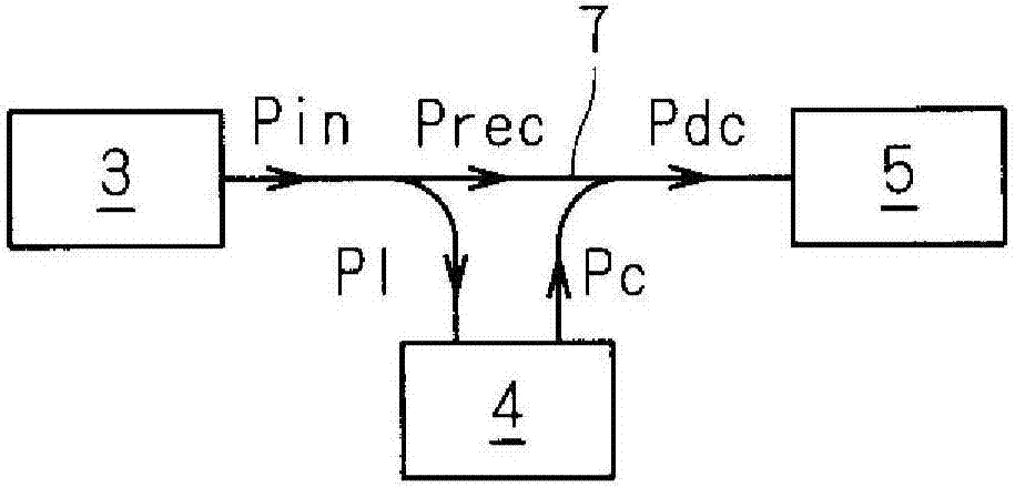
[0151] In the technology shown in Patent Document 2, in order to eliminate the above-mentioned AC component Pin^, different controls are alternately performed for each quarter cycle ((1 / 4) cycle) of the single-phase AC voltage Vin (hereinafter, also referred to as Such control is simply referred to as "quarter cycle control"). Specifically, the control of Pl=Pin^, Pc=0 and the control of Pl=0, Pc=-Pin^ are alternately performed every quarter cycle of the single-phase AC voltage Vin. Thus, during the whole period, Pdc=Pin+Pc-Pl=Pin-Pin^=(1 / 2)·Vm·Im holds true, avoiding power pulsation. This corresponds to the case of k=1 in equation (6).

[0152] In this application, following the example of Patent Document 2, the period during which the received power P1 is received from the DC link 7 (this is the period during which the cosine v...

no. 2 Embodiment approach

[0191] In the second embodiment, a case will be described in which the distribution ratio k, the rectification duty ratio drec, and the discharge duty ratio dc are different from the values ​​employed in the first embodiment.

[0192] The rectification duty ratio drec and the discharge duty ratio dc shown in equations (11) and (12) can make the DC voltage Vdc constant. If Vrec=Vm·|sin(ωt)| is taken into consideration, it can also be understood that Equation (7) holds true identically.

[0193] Among them, drec≤1, and during the grant period, |sin(ωt)|≤1 / √2, therefore, from the rectification duty cycle during the grant period shown on the right side of equation (12), it can be known that as long as the DC voltage Vdc is constant , then the value will not exceed 1 / √2 times the amplitude Vm.

[0194] Therefore, in this embodiment, a technique for increasing the ratio R of the DC voltage Vdc to the amplitude Vm (hereinafter referred to as "voltage utilization ratio R") is introdu...

no. 3 Embodiment approach

[0263] (h-1) Duty cycle setting.

[0264] The third embodiment does not employ the "quarter cycle control" employed in the first and second embodiments. That is, in the present embodiment, the rectification duty ratio drec and the discharge duty ratio dc are determined so that no distinction is made between the acceptance period and the grant period. However, as in the first and second embodiments, the rectification duty ratio drec and the discharge duty ratio dc do not depend on the distribution ratio k.

[0265] Specifically, the rectification duty cycle drec and the discharge duty cycle dc are determined by equations (27) and (28), respectively.

[0266] Formula 27

[0267]

[0268] Formula 28

[0269]

[0270]As will be described later, the voltage Vc at both ends fluctuates, but is controlled to be approximately constant. Therefore, the discharge duty ratio dc is proportional to 1+cos(2ωt), and is basically based on a frequency twice that of the single-phase AC v...


PUM


Abstract

The present invention suppresses a voltage fluctuation across the ends of a buffer capacitor of a power buffer circuit of a direct power converter in the event of a fluctuation in the electrostatic capacitance of the buffer capacitor. This control device (10) is provided with a charge control unit (103). The charge control unit (103) has an amplitude determination part (103a), a charge command generation part (103b), and charge operation control part (103c). The amplitude determination part (103a) performs at least proportional integral control with respect to the deviation (Vc) between an average voltage command value (Vc*), that is, a command for the average value of voltage (Vc) across the ends of the buffer capacitor, and the voltage (Vc) across the ends, and determines the amplitude (Im) of an input current to the converter. The charge command generation part (103b) multiplies the amplitude (Im) by a function (F (Theta)) that is determined in accordance with a discharge duty cycle (dc), a rectification duty cycle (drec), and a power distribution ratio and determines a charge command (iL*). The charge operation control part (103c) controls the charging operation of the buffer capacitor on the basis of the charge command (iL*).

Description

technical field [0001] This invention relates to a technique for controlling a direct power converter having a converter, an inverter, and a power snubber circuit connected to each other via a DC link. Background technique [0002] In order to obtain a DC voltage from a single-phase AC voltage input from a single-phase AC power supply, a full-wave rectifier circuit is generally used as a converter. However, power ripples having a frequency twice the frequency of the single-phase AC voltage exist in the output of the full-wave rectifier circuit. Therefore, in order to reduce the power ripple, a power buffer circuit for buffering power is required between the output side of the full-wave rectifier circuit and the load. [0003] Non-Patent Documents 1 to 3 and Patent Documents 1 to 4 described later disclose techniques for connecting a capacitor to a DC link via a switching element. A technique has been proposed in which this capacitor (hereinafter also referred to as "snubbe...

Claims


Application Information

Patent Timeline
IPC IPC(8): H02M7/48H02M3/155
CPCH02M1/4208H02M5/458H02M1/15H02M3/158Y02B70/10H02M1/0025H02M1/088H02M5/4585
Inventor 榊原宪一
Owner DAIKIN IND LTD
Why Eureka
Try Eureka