A displacement monitoring system and method

A displacement monitoring and code phase technology, applied in radio wave measurement systems, positioning, measurement devices, etc., can solve the problems of high cost, slow one pass, complex system structure, etc., and achieve low cost, convenient layout and simple system structure. Effect

Active Publication Date: 2018-04-10
TSINGHUA UNIV
View PDF5 Cites 0 Cited by
  • Summary
  • Abstract
  • Description
  • Claims
  • Application Information

AI Technical Summary

Problems solved by technology

However, the problem also exists in some scenarios in practical applications
The realization of laser scanning mostly adopts mechanical point-by-point scanning. Although it is generally carried out in an automated way, the speed of comprehensive scanning of the monitored structure is relatively slow; and the unit price of the instrument is high, and it is difficult to use it for long-term monitoring.
The massive data obtained by 3D laser scanning requires a lot of computing and processing to extract the characteristic parameters of the monitored structure, and then realize monitoring, so there is a big difference from the existing deformation monitoring mode based on monitoring points
GNSS technology used in deformation monitoring has the following disadvantages: GNSS receivers are located in high mountains, valleys, underground, densely built areas and deep forests, due to the occlusion of satellite signals and the influence of multipath effects, the monitoring accuracy and reliability are not high Or it cannot be monitored; when GNSS is used for dynamic deformation monitoring, since the accuracy of GNSS dynamic measurement can only reach the centimeter level, it is difficult to extract weak deformation information from the observation data; the cost of high-precision GNSS receiving equipment is relatively high, and generally more than 3 sets are required GNSS receivers work together; GNSS error sources are many, compared with traditional geodetic methods, the functional relationship between GNSS positioning results and observation values ​​is complex, and any link in the data processing process that is not properly handled will affect the final monitoring accuracy; GNSS adopts satellite "broadcasting" working mode. In displacement monitoring, a large number of positioning results still need communication links to return data, which complicates system design.
[0010] The automatic measurement distance of the total station is about one thousand meters. Large-scale monitoring requires multi-station networking, which is costly and low in equipment utilization. It is not suitable for the measurement of high-frequency vibrations.
The three-dimensional laser scanning technology is slow to scan the monitored structure in one pass; the unit price of the instrument is high, and it is difficult to use it for long-term monitoring; massive data requires a lot of calculation and processing to extract the characteristic parameters of the monitored structure, and then realize monitoring. Therefore, it is different from the existing There are big differences in deformation monitoring modes based on monitoring points
The satellite has an inherent operating cycle, and the satellite synthetic aperture radar satellite data is not real-time enough, and after the data is released, it requires a lot of calculation and processing, which is not suitable for high dynamic deformation monitoring
Ground synthetic aperture radar is expensive
GNSS satellite signals are easily blocked and affected by multipath effects; in the case of RTK, the accuracy of GNSS dynamic measurement can only reach the centimeter level, which is not applicable to micro-deformation; high-precision GNSS receiving equipment is expensive, and generally requires More than 3 GNSS receivers; the positioning data of GNSS monitoring nodes needs to be transmitted back through another data link, and the system structure is complex
The layout of the sensor requires a lot of work, not only requires good fixation, but also a solid connection with the structure to be measured, and there are difficulties in the layout of many structures
In the case of multi-node and high sampling rate, wireless sensor network has heavy node burden, it is difficult to achieve high real-time performance, and time synchronization is required

Method used


Image

  • A displacement monitoring system and method
  • A displacement monitoring system and method
  • A displacement monitoring system and method

Examples


Embodiment 1

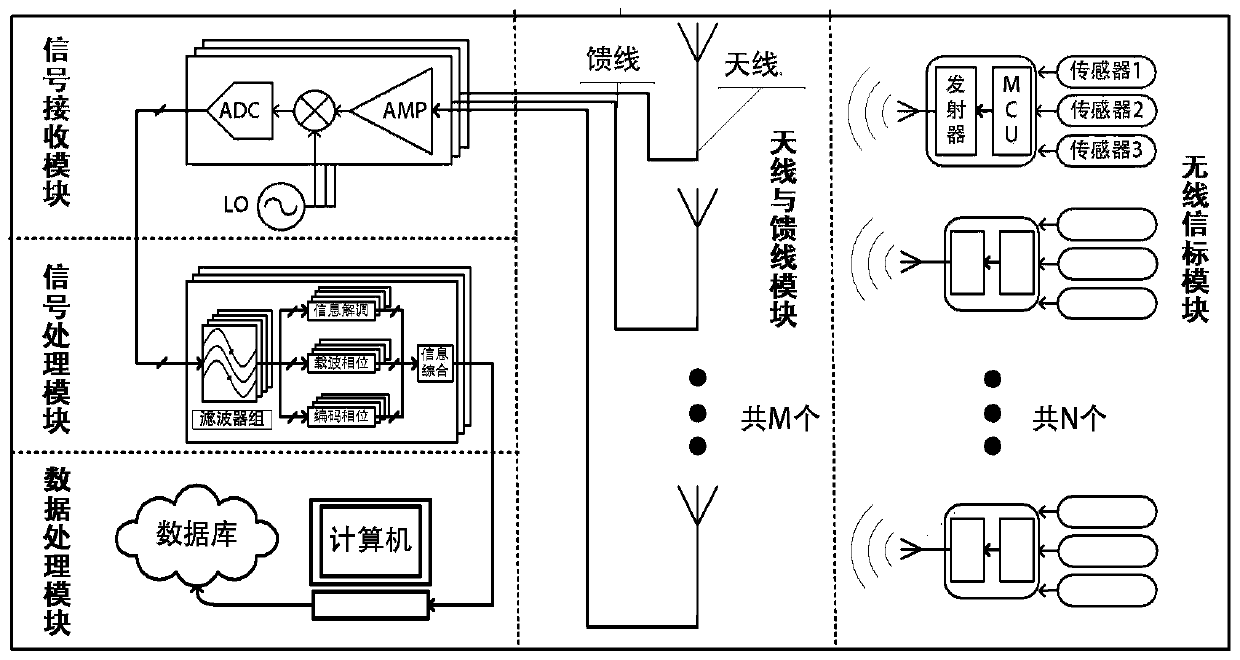
[0054] The wireless beacon module uses Arduino Pro Mini as the encoding controller. The HC-11 wireless serial port module based on the CC1101 RF transceiver chip is responsible for RF signal transmission. The working frequency band is 433MHz and the working distance is about 1000m. Since the B210 has two radio frequency channels, one-dimensional displacement monitoring can be realized.

[0055] The signal receiving module uses Ettus' USRP B210 development board, which includes radio frequency switches, amplifiers, transceivers, FPGAs and USB3.0 interfaces. The antenna adopts 433MHz 3dB gain standard helical antenna. The feeder adopts KSR400 / LMR400 coaxial cable.

[0056] The signal processing module is implemented based on the CPU, the specific hardware is a mobile workstation ThinkPadW520, the software is implemented based on the signal processing program developed by GNURadio, and the software algorithm is as described above.

Embodiment 2

[0058] The hardware of the signal processing module and signal receiving module remains unchanged, and the receiving frequency is set to 2.4GHz through software.

[0059] The wireless beacon uses a wireless module based on nRF24l01+ and works at 2.4GHz.

Embodiment 3

[0061] The signal processing module is implemented based on embedded CPU and FPGA. The specific hardware is Xilinx Zynq-7000 fully programmable SoC ZC706 evaluation board. The core device is Xilinx Zynq-7000, which contains ARM core and FPGA, which can realize high-speed signal processing.

[0062] The signal receiving module uses ADI's AD-FMCOMMS5-EBZ development board, onboard two dual-channel radio frequency transceivers, which can realize the transmission and reception of four radio frequency signals and realize three-dimensional displacement monitoring.

[0063] The wireless beacon can be implemented using example 1 or 2.


PUM


Abstract

The invention discloses a displacement monitoring system and a method. The system comprises a wireless beacon module, a signal receiving module and a signal processing module, wherein the wireless beacon module comprises N wireless beacons, is fixed to a structure to be measured and emits wireless signals; the signal receiving module comprises M receiving antennas, are used for receiving the wireless signals and converts the signals into digital signals, wherein the N is greater than or equal to 1 and the M is greater than or equal to 2; the signal processing module receives the digital signals and decomposes the signals of the different wireless beacons, carries out code phase demodulation and carrier wave phase demodulation processing respectively and finally integrally receives a code phase demodulation result and a carrier wave phase demodulation result of the signals between each two antennas so as to acquire a displacement monitoring result. By using the system and the method in the invention, millimeter precision displacement monitoring can be realized; the system structure is simple, time synchronization is not needed, laying is convenient and cost is low; and there is no significant change along with increase of the number of nodes.

Description

Technical field [0001] The invention relates to a radio positioning engineering measurement sensor network, in particular to a high-precision displacement monitoring system. Background technique [0002] Displacement monitoring is widely used in structural health monitoring, including artificial structures such as bridges and dams and natural structures such as mountains and glaciers. The monitoring method is to measure the displacement of key points of the structure over time and the external environment to achieve the quality of the measured structure The purpose of assessment, safety warning, etc. [0003] The total station (Total Station) is a commonly used optical-electromechanical integrated instrument in modern surveying and mapping. The working principle is to use high-precision photoelectric ranging and electronic theodolite to realize direction finding and ranging of remote control points. Because of its good directivity, lasers are very suitable for ranging. Common tot...

Claims


Application Information

Patent Timeline
Patent Type & Authority Patents(China)
IPC IPC(8): G01S5/02
CPCG01S5/02
Inventor 王力军王正博张建伟孙晓林孙思忱
Owner TSINGHUA UNIV
Why Eureka
Try Eureka