

Cutting machine with pressing block mechanism
A cutting machine and frame technology, applied in metal processing and other directions, can solve the problems of difficult adjustment of the oil cylinder stroke of the cutting machine, large wear of the cutting machine blade, heavy tool weight, etc., so as to reduce manual operations and improve production. The effect of high efficiency and high tool change efficiency
- Summary
- Abstract
- Description
- Claims
- Application Information
AI Technical Summary
Problems solved by technology
Method used
Image

Examples
Embodiment 1
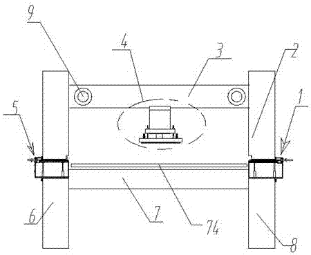
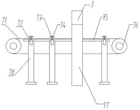
[0026] Such as Figure 1 to Figure 8 Shown a kind of cutting machine with briquetting mechanism, comprises upper frame 3, left frame 6, right frame 8, is provided with cutting mechanism 4 on described upper frame 3, and described cutting Cutting mechanism 4 can move left and right on described upper frame 3 through transmission mechanism, also be provided with cutting table 7 between described left frame 6 and right frame 8, described cutting table 7 comprises The conveying rollers 76 arranged at the front and rear ends are provided with the conveying belt 71 on the conveying rollers 76 at the front and rear ends.
[0027] At least three sets of briquetting brackets 78 are evenly distributed at the left and right ends of the conveyor belt 71 , and each set of briquetting brackets 78 is symmetrically distributed at both ends of the conveyor belt 71 . A pressing table 75 is also provided between the briquetting brackets 78, and the pressing table 75 is arranged at the lower end...
Embodiment 2
[0038] As a supplement to Embodiment 1 of the present invention, racks are provided at the connections between the left frame 6 and the right frame 8 and the upper frame 3, and the upper frame 3 and the left frame 6 and the right frame 8 A stepping motor and a gear are respectively arranged at the connection. The stepper motor rotates to drive the gear to move on the rack, so as to realize the up and down movement of the upper frame, so that the appropriate stroke can be adjusted according to the thickness of the cutting material to ensure that the material can be cut without damaging the conveyor belt.
[0039] The invention provides a cutting machine with a briquetting mechanism. By setting the briquetting mechanism, the briquetting mechanism can be pressed down when cutting is required, thereby pressing the material to be cut and preventing the material from moving. , affecting the cutting effect; by setting the automatic tool change mechanism, the tool can be automatically...
PUM
 Abstract
Description
Claims
Application Information