Constant-temperature hydraulic station

A hydraulic station and constant temperature technology, which is applied in the field of hydraulic systems, can solve problems such as accelerated mechanical wear, accelerated oil quality deterioration, and reduced efficiency, and achieves the effects of stabilizing power performance, prolonging service life, and reducing maintenance costs

Inactive Publication Date: 2017-08-22
成都寇客科技有限公司
9 Cites 4 Cited by

AI-Extracted Technical Summary

Problems solved by technology

Excessive oil temperature in the hydraulic system will lead to: the viscosity of the oil is reduced, which is easy to cause leakage and the efficiency is reduced; Premature aging of rubber hose, etc.
The oil ...

Method used

Adopt antifreeze as cooling circulation medium, first fin radiator 20 can fully carry out heat exchange with the hydraulic oil of high temperature and low temperature antifreeze, cooling pump 31 provides circulating power to the antifreeze in heat dissipation assembly, ring water The chamber 41 increases the cooling surface area of ​​the antifreeze, thereby retaining heat on the shell of the annular water chamber 41, and the fan 42 takes away the temperature of the annular water chamber 41, thereby reducing the temperature of the antifreeze, and the low-temperature antifreeze passes through the antifreeze inlet pipe The road 33 enters the fin radiator 20 to exchange heat for the hydraulic oil. The cooling efficiency of ...

Abstract

The invention discloses a constant-temperature hydraulic station. The constant-temperature hydraulic station comprises an oil tank and a heat dissipation assembly accommodating an anti-freezing solution, wherein the heat dissipation assembly comprises a finned radiator, a cooling pump and an air cooler, the finned radiator is arranged in the oil tank, and the cooling pump and the air cooler are arranged outside the oil tank. The heat dissipation assembly comprises the finned radiator, the cooling pump and the air cooler, the anti-freezing solution is adopted as a cooling circulation medium, the cooling efficiency of the hydraulic station is far higher than that of an existing conventional hydraulic station, temperature of hydraulic oil is controlled in a range of 50-55 DEG C, so that a sealing ring is prevented from aging, maintenance cost of main equipment is reduced, power performance is stabilized, high-temperature emulsification of the hydraulic oil is prevented, the service life of the hydraulic oil is prolonged, and the use amount of the hydraulic oil is reduced.

Application Domain

Technology Topic

Image

  • Constant-temperature hydraulic station
  • Constant-temperature hydraulic station

Examples

  • Experimental program(1)

Example Embodiment

[0018] The present invention will be further described below in conjunction with accompanying drawing:
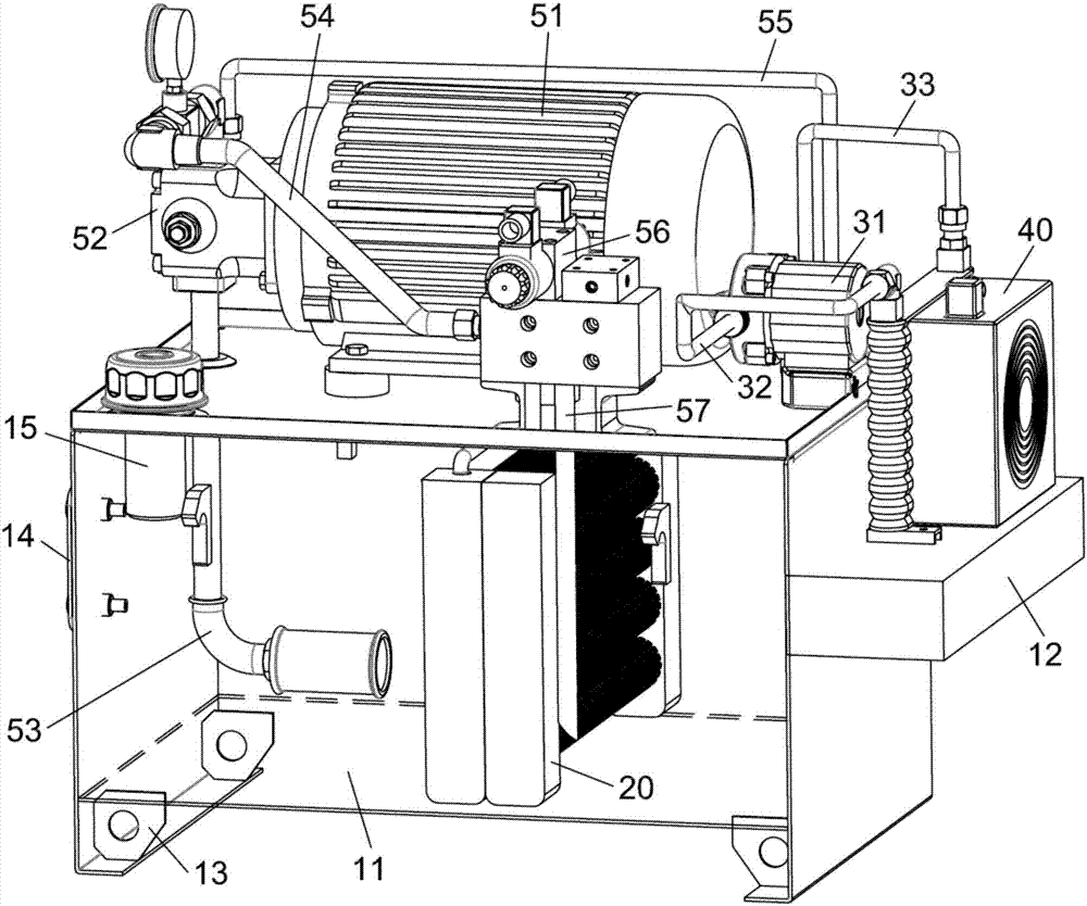
[0019] Refer to attached figure 1 And attached figure 2 , the present invention provides a constant temperature hydraulic station, including a fuel tank 11 and a cooling assembly filled with antifreeze, the cooling assembly includes a finned radiator 20, a cooling pump 31 and an air cooler 40, the finned radiator 20 is arranged in the middle of the oil tank 11, The cooling pump 31 and the air cooler 40 are provided outside the oil tank 11 .
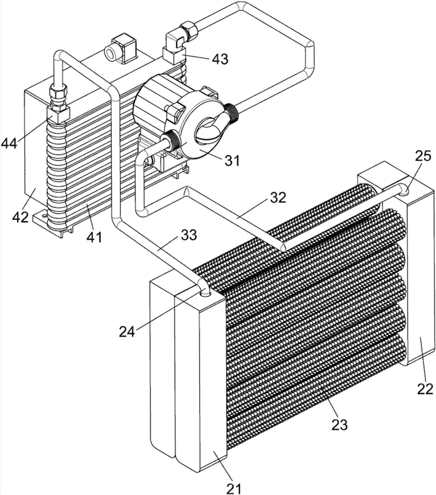
[0020] The air cooler 40 includes an annular water chamber 41 and a fan 42. The annular water chamber 41 is arranged behind the fan 42. A water chamber water inlet 43 is arranged on one side of the annular water chamber 41, and a water chamber water outlet 44 is arranged on the other side.
[0021] The fin radiator 20 comprises a first bracket 21 and a second bracket 22 and a plurality of finned heat pipes 23, the finned heat pipes 23 are connected between the first bracket 21 and the second bracket 22, and the first bracket 21 is provided with a cooling The radiator water inlet 24, the second bracket 22 is provided with the radiator water outlet 25, the antifreeze liquid outlet pipeline 32 is arranged between the radiator water outlet 25 and the water chamber water inlet 43, the water chamber water outlet 44 and the radiator water inlet An antifreeze liquid inlet pipeline 33 is arranged between 24, and a cooling pump 31 is arranged in the antifreeze liquid outlet pipeline 32.
[0022] Antifreeze is used as the cooling circulation medium. First, the finned radiator 20 can fully exchange heat between the high-temperature hydraulic oil and the low-temperature antifreeze. The cooling pump 31 provides circulation power for the antifreeze in the heat dissipation assembly. The cooling surface area of ​​the antifreeze is large, so that the heat stays on the shell of the annular water chamber 41, and the fan 42 takes away the temperature of the annular water chamber 41, thereby reducing the temperature of the antifreeze. The low-temperature antifreeze enters through the antifreeze inlet pipeline 33 The fin radiator 20 performs heat exchange on the hydraulic oil. The cooling efficiency of this device is much higher than that of the existing conventional hydraulic station, and the temperature of the hydraulic oil is controlled between 50°C and 55°C, thereby preventing the aging of the sealing ring and reducing the cost of the host equipment. Reduce maintenance costs, stabilize power performance, prevent high-temperature emulsification of hydraulic oil, prolong the service life of hydraulic oil, and reduce the amount of hydraulic oil used.
[0023] In this embodiment, a support plate 12 is fixedly connected to the side of the fuel tank 11 , and the air cooler 40 is fixedly connected to the upper surface of the support plate 12 , thereby stabilizing the air cooler 40 .
[0024] In this embodiment, the cooling pump 31 is fixedly connected to the upper surface of the oil tank 11 to make reasonable use of the existing space.
[0025] In this embodiment, a motor 51 is fixedly connected to the top of the oil tank 11, an oil pump 52 is fixedly connected to the end of the motor 51, an oil suction pipe 53 leading to the oil tank 11 is connected below the oil pump 52, and an oil outlet pipe 54 is connected above the oil pump 52. The side is connected with an oil discharge pipe 55 leading to the oil tank 11 , and the oil discharge pipe 55 prevents hydraulic oil from accumulating in the oil pump 52 .
[0026] In this embodiment, a reversing valve 56 is connected to the oil outlet pipe 54, and the reversing valve 56 is connected to an oil return pipe 57 leading to the oil tank 11. The hydraulic oil in the oil outlet pipe 54 can be guided back to the oil tank 11 through the reversing valve 56. middle.
[0027] In this embodiment, support frames 13 are fixedly connected to both sides of the bottom of the fuel tank 11, and the support frames 13 can support the weight of the entire device.
[0028] In this embodiment, an oil level gauge 14 is provided on the side of the fuel tank 11, and an air filter 15 connected to the fuel tank 11 is provided above the fuel tank 11. The air filter 15 can filter the air in the fuel tank 11 to provide hydraulic oil. good workspace.

PUM

no PUM

Description & Claims & Application Information

We can also present the details of the Description, Claims and Application information to help users get a comprehensive understanding of the technical details of the patent, such as background art, summary of invention, brief description of drawings, description of embodiments, and other original content. On the other hand, users can also determine the specific scope of protection of the technology through the list of claims; as well as understand the changes in the life cycle of the technology with the presentation of the patent timeline. Login to view more.

Similar technology patents

Multifunctional warmer-dryer

PendingCN107366142APrevent agingImprove safety and qualityAir heatersTextiles and paperClothes hangerEngineering
Owner:中山蓝网物联技术有限公司

PE modified material and preparation method thereof

InactiveCN109694512AAvoid approachingPrevent agingPolytetrafluoroethyleneWater environment
Owner:高邮市汉升高分子材料有限公司

Prunus humilis fruit beverage

InactiveCN109170399AEliminate free radicals in the bodyPrevent agingFood thermal treatmentNatural extract food ingredientsFoods beveragesHawthorn fruit
Owner:北京沛时特医食品科技有限公司

Classification and recommendation of technical efficacy words

  • Reduce maintenance costs
  • Prevent aging

Rapid steam generator based on induction heating

PendingCN109539219APrevent agingAvoid rust lossSteam generation heating methodsBoiler cleaning apparatusVapor generatorElectromagnetic induction
Owner:QINGDAO TECHNOLOGICAL UNIVERSITY
Why Eureka
Try Eureka