
Flame three-dimensional temperature field measurement system and method thereof based on optical field stratified imaging technique

A layered imaging, three-dimensional temperature technology, applied in optical radiation measurement, radiation pyrometry, measurement devices, etc. Distribution has little effect

Active Publication Date: 2017-08-22
SOUTHEAST UNIV
View PDF9 Cites 16 Cited by
  • Summary
  • Abstract
  • Description
  • Claims
  • Application Information

AI Technical Summary

Problems solved by technology

Based on the optical layered imaging temperature measurement method of traditional camera shifting or zooming, the three-dimensional light-emitting object is regarded as a combination of multiple parallel two-dimensional light-emitting slices, and the original image of the slice is formed by focusing on a certain plane. Superimpose the image with defocused images of other faults, and invert the image to obtain the original image information of each fault. This method has simple equipment and fast calculation speed, but every time the flame is shot, the motor drives the camera to change the shooting position of the camera. Or drive the lens to zoom, and the flame changes every moment. There is a large delay error in the image sequence acquisition method of this method

Method used


Image

  • Flame three-dimensional temperature field measurement system and method thereof based on optical field stratified imaging technique
  • Flame three-dimensional temperature field measurement system and method thereof based on optical field stratified imaging technique
  • Flame three-dimensional temperature field measurement system and method thereof based on optical field stratified imaging technique

Examples


Embodiment Construction

[0029] The present invention will be further elaborated below in conjunction with the accompanying drawings and specific embodiments. It should be understood that these embodiments are only used to illustrate the present invention and are not intended to limit the scope of the present invention. After reading the present invention, those skilled in the art will fall within the limits of the appended claims of the present application to the modification of various equivalent forms of the present invention range. In this embodiment, the light field camera adopts the R29 light field camera of German raytrix company.

[0030] A kind of flame three-dimensional temperature field method based on light field camera layered imaging technology of the present invention comprises the following steps:

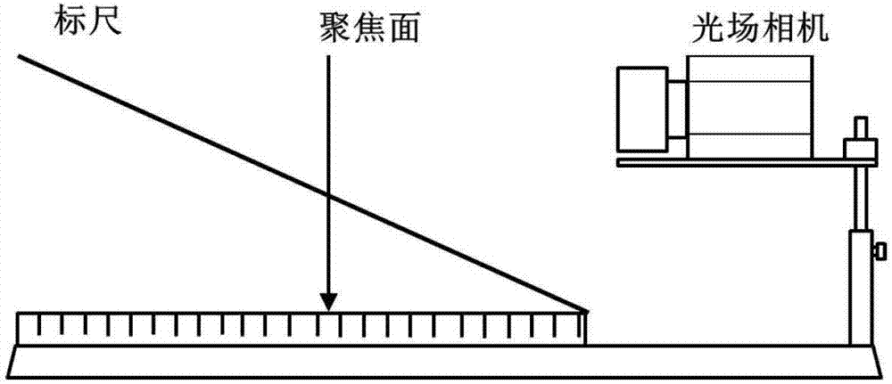
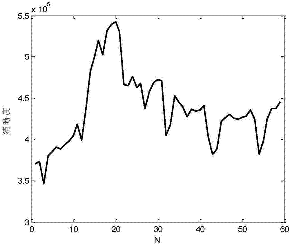
[0031] Step 1: Use such as figure 1 The method shown refocuses the inclined scale with scales to obtain a picture that contains distance information and has distinct clarity. Divide the c...


PUM


Abstract

The invention discloses a flame three-dimensional temperature field measurement system and a flame three-dimensional temperature field measurement method based on an optical field layered imaging technology. The flame three-dimensional temperature field measurement system comprises a precise optical platform, a sliding rail, an optical field camera and a computer, wherein the optical field camera is used for acquiring four-dimensional optical field information of flame; and the computer is used for storing information and carrying out calculation and analysis. The flame three-dimensional temperature field measurement system and the flame three-dimensional temperature field measurement method acquire three-dimensional flame optical field information by means of the optical field camera, and carries out digital refocusing treatment and image deconvolution treatment to obtain a flame radiation intensity value on each layer, thereby acquiring temperature field of the flame. The flame three-dimensional temperature field measurement system can acquire information of each focusing plane through one-step shooting without zooming or changing a position of the camera, and can realize high-time-precision optical non-contact type measurement of the ever-changing flame.

Description

technical field [0001] The invention belongs to the technical field of flame temperature measurement, and in particular relates to a three-dimensional temperature field measurement system of a combustion flame based on optical field layered imaging and a method thereof. Background technique [0002] The light field camera arranges a microlens array between the main lens and the image sensor, and the imaging system can simultaneously distinguish the intensity information and direction information of the light, so that the sensor can collect the four-dimensional light field data of the subject. The light field camera has the characteristics of first taking pictures and then focusing, which can effectively capture a wider range of scene depth and display the 3D structure of the real scene. Light field imaging technology is gradually used in aerospace, 3D reconstruction, security surveillance and many other fields. [0003] The flame temperature field distribution is an importan...

Claims


Application Information

Patent Timeline
IPC IPC(8): G01J5/00G01J5/08G01J5/50G01J5/60
CPCG01J5/00G01J5/0018G01J5/0806G01J5/60G01J2005/0077G01J5/485G01J5/03
Inventor 许传龙赵文超张彪孙俊王式民
Owner SOUTHEAST UNIV
Learn More