Double-valve connecting rod handle pulse thrombolytic catheter post-push syringe

A syringe and handle technology, applied in the field of medical devices, can solve the problems of spring fatigue deformation, fatigue of medical staff, affecting the effect of thrombolysis, etc., and achieve the effect of improving the success rate, smooth pipeline, reducing infection rate and treatment cost

Active Publication Date: 2017-08-25
SHANGHAI PUYI MEDICAL INSTR
View PDF13 Cites 2 Cited by
  • Summary
  • Abstract
  • Description
  • Claims
  • Application Information

AI Technical Summary

Problems solved by technology

[0003] At present, for thrombolytic catheter equipment, a relatively slender catheter is originally connected to the front of the equipment. When the syringe is pushed by hand for blood thrombolytic therapy, the pressure is too small, uncontrollable, and unable to last for a long time, which affects the thrombolytic effect. In addition, the implementation of the aforementioned Auxiliary equipment commonly used in this type of treatment includes a hand-pressed syringe, which compresses the spring through the handle to eject the medicine in the syringe from the outlet. Because the rear spring is fatigued and deformed during use, it is often easy to get stuck, and it takes a long time and high Pressing the handle frequently, the operation intensity is relatively high, and the medical staff are tired. There is no better alternative equipment or automatic injection technology disclosed

Method used


Image

  • Double-valve connecting rod handle pulse thrombolytic catheter post-push syringe
  • Double-valve connecting rod handle pulse thrombolytic catheter post-push syringe
  • Double-valve connecting rod handle pulse thrombolytic catheter post-push syringe

Examples


Embodiment 1

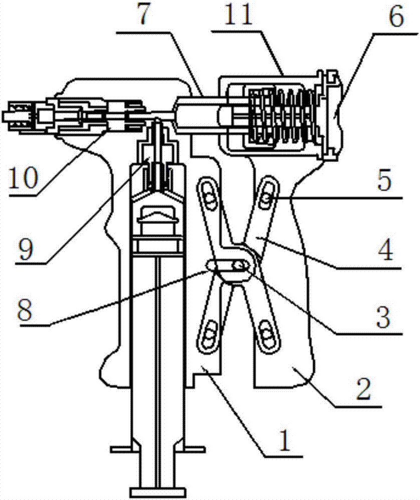
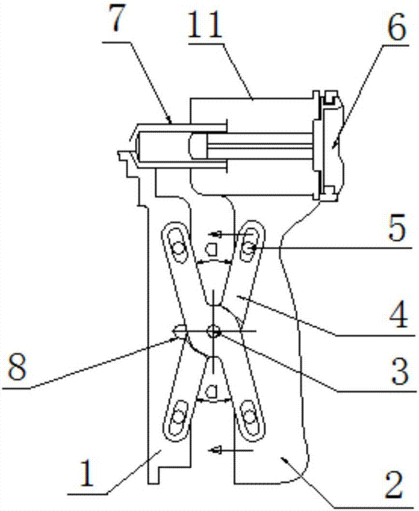
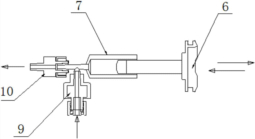
[0022] Embodiment 1: as attached figure 1 As shown, the main body handle 1 and the sliding handle 2 are connected in parallel through two sets of connecting rods 4 cross-hinged with the hinge shaft 3, the hinge shaft 3 is installed in the chute 8 opened in the middle of the main body handle 1, and the two connecting rods 4 The ends are respectively slidably connected to the main body handle 1 or the sliding handle 2 through their corresponding pin shafts 5, and the liquid injection inlet check valve 9 and the liquid injection outlet check valve 10 connected in the same direction are fixedly connected to the main body handle 1, wherein, The outlet end of the liquid injection outlet check valve 10 is located on the front side of the upper part of the main body handle 1. At the same time, the front end of the liquid injection pipe 7 is fixedly connected between the liquid injection import check valve 9 and the liquid injection outlet check valve 10, behind the liquid injection pip...


PUM


Abstract

The invention provides a double-valve connecting rod handle pulse thrombolytic catheter post-push syringe. A main body handle (1) and a sliding handle (2) are connected in a parallel mode through two groups of connecting rods (4) which are cross-hinged by hinge shafts (3); a liquid injection importing single-way valve (9) and a liquid injection exporting single-way valve (10) are fixedly connected to the main body handle (1), wherein the liquid injection importing single-way valve (9) and the liquid injection exporting single-way valve (10) are connected in a same direction; the front end of a liquid injection pipe (7) is fixedly connected between the liquid injection importing single-way valve (9) and the liquid injection exporting single-way valve (10); a post-sleeve pipe (11) is sleeved outside the rear section of the liquid injection pipe (7) through a bushing spring; the front section of a push rod (6) from rear to front is inserted into the rear section of the liquid injection pipe (7); the rear end of the push rod (6) is connected with the post-sleeve pipe (11). The syringe is transferred horizontally and manually through the separating handle double connecting rod, and cooperates with a double single-way valve pulse pump at the same time to send injection liquid, the structure is compact, joint and not loose to ensure flexible transfer and movement, and the liquid injection push rod advances and retreats freely, the use is safe and reliable, the success rate of thrombus is improved and the infection rate and treatment costs are reduced.

Description

technical field [0001] The invention relates to an IPC classification A61M medical device for injecting a medium into or onto a human body, in particular to a push-back injector for a pulse thrombolysis catheter with a double-valve connecting rod handle. Background technique [0002] Currently, arterial thrombosis may be treated with thrombolytic catheter technology. For example, the nursing measures for thrombolytic catheter treatment of acute lower extremity arterial thrombosis are more typical. Acute lower extremity arterial thrombosis refers to the fact that an embolus falls off from the heart or proximal arterial wall, or enters the artery from the outside, and is pushed to the far side by the blood flow, blocking the arterial blood flow. It is a pathological process that causes limb ischemia and even necrosis due to blood flow. It is named for its sudden onset. Disease treatment adopts the seldinger method, that is, use a puncture needle with a needle core to penetrat...

Claims


Application Information

Patent Timeline
Patent Type & Authority Applications(China)
IPC IPC(8): A61M5/178A61M5/315
CPCA61M5/178A61M5/315
Inventor 王国强
Owner SHANGHAI PUYI MEDICAL INSTR
Why Eureka
Try Eureka