Series hybrid electric vehicle energy storage structure based on elastic energy storage and energy distribution method

A series hybrid and electric vehicle technology, applied in the direction of hybrid vehicles, motor vehicles, power plants, etc., can solve the problems of energy waste, low efficiency, cost increase, etc., and achieve the effect of simple control method and reduced use cost

Inactive Publication Date: 2017-08-25
TSINGHUA UNIV
View PDF5 Cites 2 Cited by
  • Summary
  • Abstract
  • Description
  • Claims
  • Application Information

AI Technical Summary

Problems solved by technology

[0003] The present invention aims to solve the problems of low efficiency in the existing electric vehicle drive energy storage structure, and the cost increase and energy w...

Method used


Image

  • Series hybrid electric vehicle energy storage structure based on elastic energy storage and energy distribution method
  • Series hybrid electric vehicle energy storage structure based on elastic energy storage and energy distribution method
  • Series hybrid electric vehicle energy storage structure based on elastic energy storage and energy distribution method

Examples


specific Embodiment approach 1

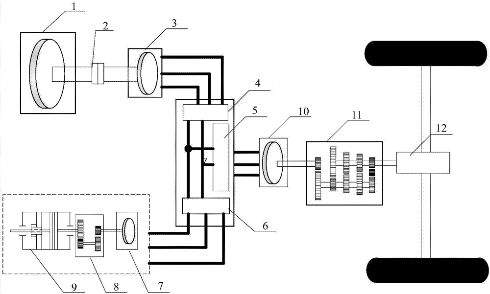
[0029] Specific implementation mode 1. Combination figure 1 This embodiment will be described. The elastic energy storage-based energy storage structure of a series hybrid electric vehicle described in this embodiment includes an engine 1 , a shaft connector 2 , a generator 3 , a rectifier circuit 4 , and a No. 1 bidirectional inverter 5 , No. 2 bidirectional inverter 6, elastic energy storage system, No. 2 motor 10, No. 2 gearbox 11 and differential 12; the elastic energy storage system includes No. 1 motor 7, No. 1 gearbox 8 and elastic energy storage tank 9;

[0030] The output shaft of the engine 1 is coaxially connected to the input shaft of the generator 3 through the shaft connector 2, the current signal output end of the generator 3 is connected to the current signal input end of the rectifier circuit 4, and the DC signal output end of the rectifier circuit 4 is connected to a The DC signal terminal of the No. 2 bidirectional inverter 5 and the DC signal terminal of t...

specific Embodiment approach 2

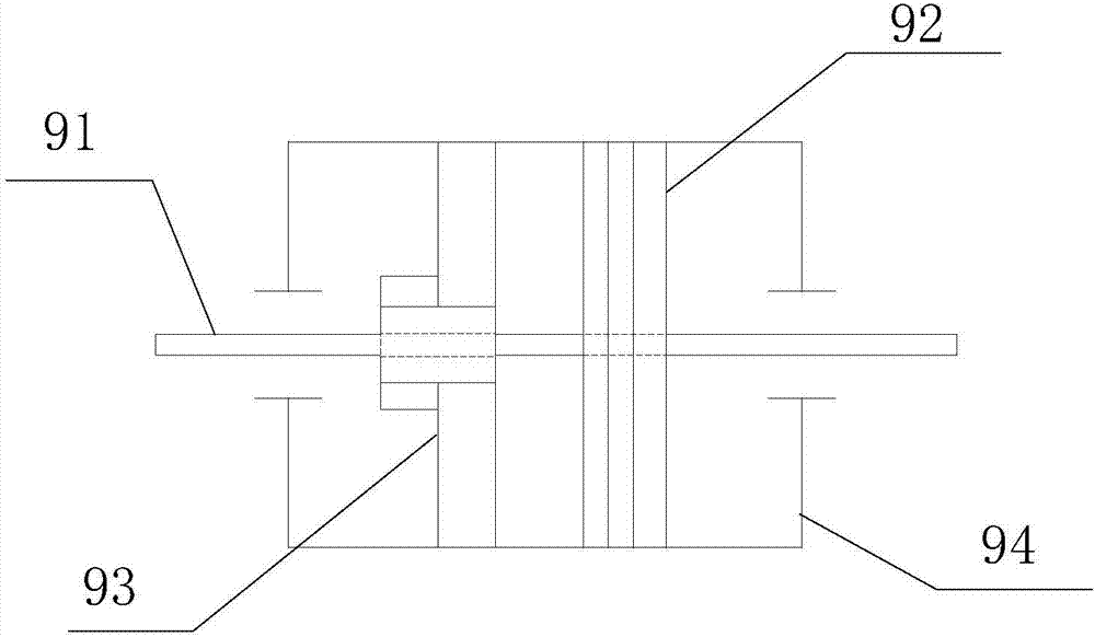
[0033] Specific embodiment 2. Combination figure 2 and image 3 This embodiment is described. This embodiment is a further description of the energy storage structure of the series hybrid vehicle based on elastic energy storage described in the specific embodiment 1. The elastic energy storage tank 9 includes a No. 1 transmission shaft 91 and an energy storage scroll spring 92. , brake 93, No. 1 box 94 and tension sensor 95;

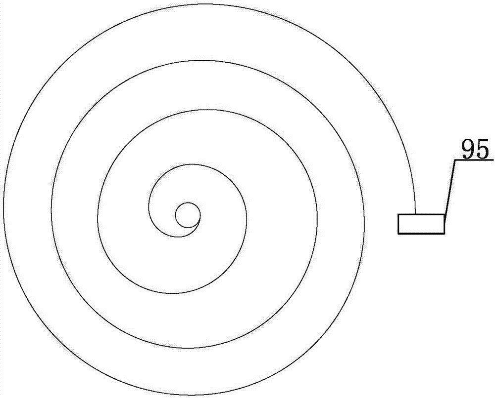
[0034] The No. 1 drive shaft 91 is located in the middle of the No. 1 case 94 and transversely passes through the No. 1 case 94. The energy storage scroll spring 92, the brake 93 and the tension sensor 95 are all arranged in the No. 1 case 94. 92 and the brake 93 are both sleeved on the No. 1 transmission shaft 91, the tension sensor 95 is fixed on the outer end of the energy storage scroll spring 92, and the energy storage scroll spring 92 and the brake 93 are not in contact.

specific Embodiment approach 3

[0035] Specific embodiment three, combination Figure 4 This embodiment is described. This embodiment is a further description of the energy storage structure of the series hybrid vehicle based on elastic energy storage described in the specific embodiment 1. The brake 93 includes a fixed spring 931, a brake tumbler 932, a spring clip 933, Brake wheel 934, No. 2 drive shaft 935, switch tube group 937, permanent magnet 938, electromagnet 939 and No. 2 box;

[0036] The brake wheel 934 is sleeved on the No. 2 transmission shaft 935, and the upper edge of the brake wheel 934 is equally spaced with four "U"-shaped grooves, and the four "U"-shaped grooves are used for inserting the brake tumbler 932. , the end of the stopper 932 is embedded with a permanent magnet 938, the permanent magnet 938 is clamped on the vertical partition in the No. 2 box, and there is a set between the left inner wall of the No. 2 box and the partition There is a fixed spring 931, the upper and lower inne...


PUM


Abstract

The invention relates to a series hybrid electric vehicle energy storage structure based on elastic energy storage and an energy distribution method and belongs to the technical field of hybrid electric vehicles. The problem that cost increasing and energy source waste caused by a plurality of times of battery replacement existing in an electric vehicle drive energy storage structure is solved. According to the series hybrid electric vehicle energy storage structure based on elastic energy storage and the energy distribution method, energy storage assisting is conducted through elastic energy storage, and an engine works in an efficient and low-emission area as much as possible; energy transmitting is conducted through electric energy conversion, so that a control method is simple and efficient; and meanwhile an elastic energy storage system is used as the energy storage structure, pollution of a chemical battery on the environment is avoided, the service life is longer than that of the chemical battery, and use cost of a vehicle is indirectly reduced. The series hybrid electric vehicle energy storage structure based on elastic energy storage and the energy distribution method are suitable for energy storage of the hybrid electric vehicles.

Description

technical field [0001] The invention belongs to the technical field of hybrid vehicles. Background technique [0002] The traditional hybrid vehicle uses the combination of APU and power battery as the energy storage structure of the vehicle. This structure requires a large number of batteries to meet the needs of energy storage, and with the increase of the number of charge and discharge cycles, the battery performance will be reduced by as much as If the expected requirements are not met, the traditional solution is to replace the battery for the hybrid vehicle, which increases the cost of the vehicle, and the production of the battery and the disposal of the waste battery will cause some pollution to the environment. SUMMARY OF THE INVENTION [0003] The present invention proposes a series hybrid vehicle energy storage structure based on elastic energy storage in order to solve the problems of low efficiency in the existing electric vehicle driving energy storage struct...

Claims


Application Information

Patent Timeline
IPC IPC(8): B60K6/30B60K6/46
CPCB60K6/30B60K6/46Y02T10/62
Inventor 杜玖玉欧阳明高李建秋石文文卢兰光
Owner TSINGHUA UNIV
Why Eureka
Try Eureka