
Afterburner nozzle layout method

A technology of afterburner and layout method, which is applied in special data processing applications, instruments, electrical digital data processing, etc. It can solve problems such as error, mismatch of oxygen flow distribution, and inability to consider oxygen flow distribution, etc., so as to improve afterburner Effects of combustion efficiency, improvement of design quality and design accuracy

Active Publication Date: 2017-08-25
AECC SHENYANG ENGINE RES INST
View PDF3 Cites 3 Cited by
  • Summary
  • Abstract
  • Description
  • Claims
  • Application Information

AI Technical Summary

Problems solved by technology

In the nozzle layout design, the traditional method is to approximate the flow area of ​​the characteristic cross-section, and cannot consider the oxygen flow distribution after the mixing of the inner and outer streams.
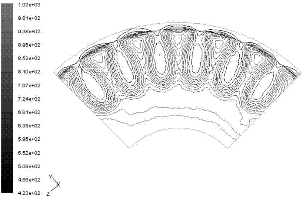
For the mixed intake afterburner, the degree of mixing of inner and outer airflows is large, and the key parameters reflecting the oxygen flow rate, such as the velocity, density, and oxygen concentration of the two airflows, have changed greatly (see figure 2 ), if the traditional area ratio method is used to design the nozzle layout, it can only be approximated as a uniform air flow, which will make the afterburner nozzle layout not match the actual oxygen flow distribution, which will bring large errors and affect the performance of the afterburner

Method used


Image

  • Afterburner nozzle layout method
  • Afterburner nozzle layout method
  • Afterburner nozzle layout method

Examples


Embodiment Construction

[0017] To make the objectives, technical solutions, and advantages of the implementation of the present invention clearer, the technical solutions in the embodiments of the present invention will be described in more detail below in conjunction with the accompanying drawings in the embodiments of the present invention. In the drawings, the same or similar reference numerals indicate the same or similar elements or elements with the same or similar functions. The described embodiments are part of the embodiments of the present invention, rather than all of the embodiments. The embodiments described below with reference to the accompanying drawings are exemplary, and are intended to explain the present invention, but should not be construed as limiting the present invention. Based on the embodiments of the present invention, all other embodiments obtained by those of ordinary skill in the art without creative work shall fall within the protection scope of the present invention.

...


PUM


Abstract

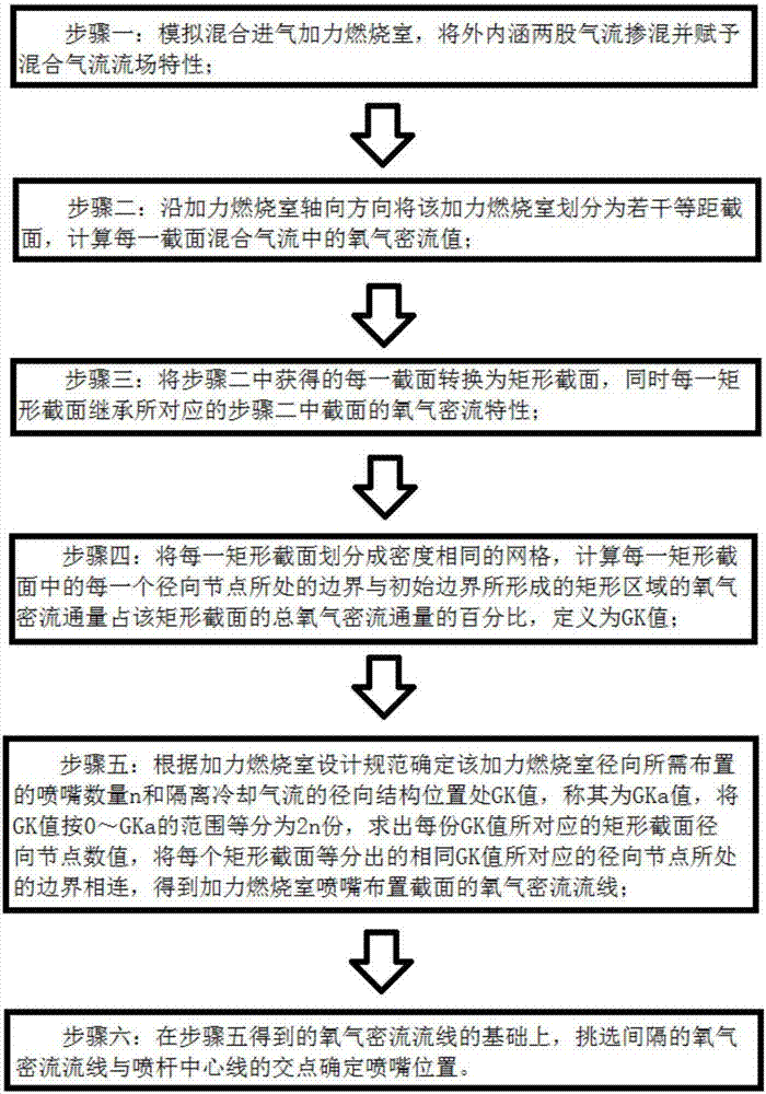
The invention provides an afterburner nozzle layout method. According to the method, flow field simulation is performed to obtain a plurality of equidistant sections with axial coordinates being constants; an oxygen dense flow value in each section airflow is calculated; each section is converted into a rectangular section, and original dense flow characteristics are inherited; the percentage GK of dense flow flux in a rectangular region formed by each radial node of each section and an initial boundary in total dense flow flux is calculated; the number n of nozzles needed in the radial direction and a GK value GKa at a radial structure position for isolating cooling airflow are determined according to design specifications; the GK value is equally divided into 2n parts according to the range from 0 to GKa, and radial coordinates corresponding to each part of the GK value at a demarcation point are solved; the radial positions corresponding to the same equally-divided GK value of each section are connected to obtain an oxygen dense flow line; and alternate intersection points of the oxygen dense flow line and a spray rod center line are selected to determine nozzle positions. Through the method, fuel and oxygen participating in burning can be finely matched and premixed uniformly, and the method is beneficial for improving afterburning efficiency.

Description

Technical field [0001] The invention belongs to the field of aeroengines, and particularly relates to an afterburner part, in particular to a nozzle layout method for an afterburner. Background technique [0002] In the design of the afterburner, the refinement of the fuel nozzle layout will directly affect the performance of the afterburner. In the nozzle layout design, the traditional method is approximately divided according to the characteristic cross-sectional flow area, and cannot consider the oxygen flow distribution after the two airflows of the inner and outer culverts are mixed. For the mixed-intake afterburner, the mixing degree of the inner and outer culvert airflow is large, and the key parameters reflecting the oxygen flow rate such as the speed, density, and oxygen concentration of the two airflows have undergone major changes (see figure 2 ), if the traditional area rate method is used to design the nozzle layout, it can only be approximated as a uniform air flow,...

Claims


Application Information

Patent Timeline
Patent Type & Authority Applications(China)
IPC IPC(8): G06F17/50
CPCG06F30/17
Inventor 徐兴平朱健张孝春李江宁高家春刘涛
Owner AECC SHENYANG ENGINE RES INST
Learn More