
Super junction terminal structure and preparation method thereof

A junction terminal and terminal technology, which is applied in the field of super junction terminal structure and its preparation, can solve the problems of increasing the mask plate and increasing the complexity of the process, and achieve the effects of saving chip area, avoiding the concentration of local electric field, and improving the potential distribution

Inactive Publication Date: 2017-08-25
江苏芯长征微电子集团股份有限公司 +1
View PDF5 Cites 0 Cited by
  • Summary
  • Abstract
  • Description
  • Claims
  • Application Information

AI Technical Summary

Problems solved by technology

[0006] However, in the super junction structure of the deep groove structure, the cooperation of the micromachining system is required, and the number of masks is increased at the same time, which increases the complexity of the process

Method used


Image

  • Super junction terminal structure and preparation method thereof
  • Super junction terminal structure and preparation method thereof
  • Super junction terminal structure and preparation method thereof

Examples


Embodiment Construction

[0039] The present invention will be further described below in conjunction with specific drawings and embodiments.

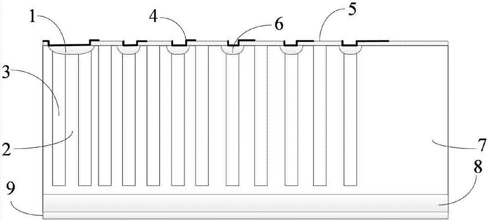
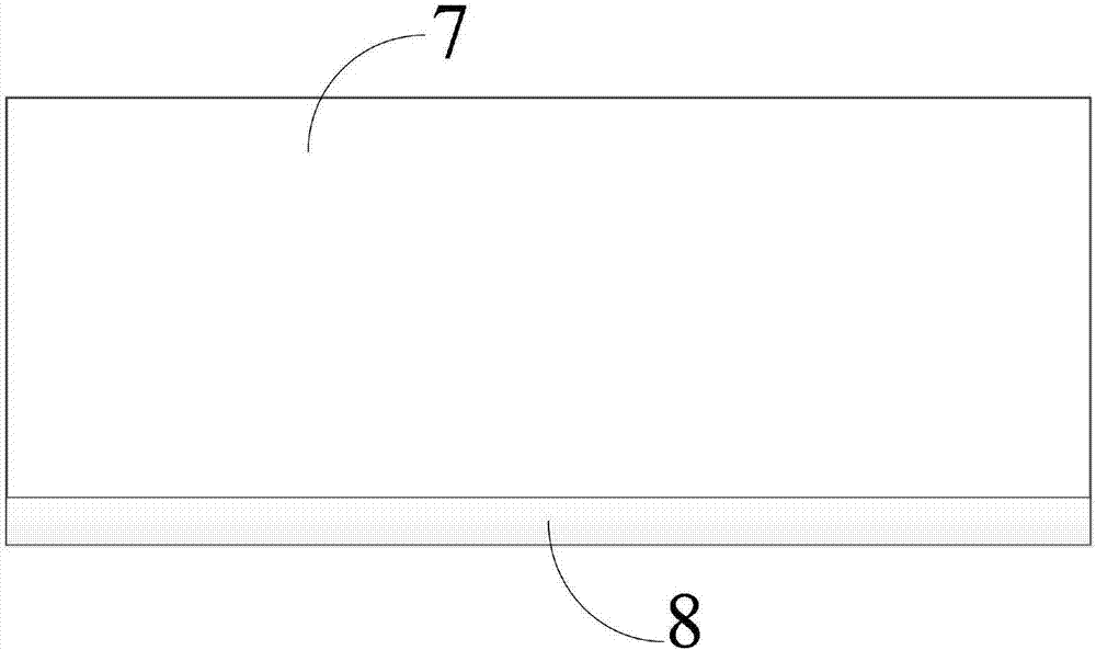
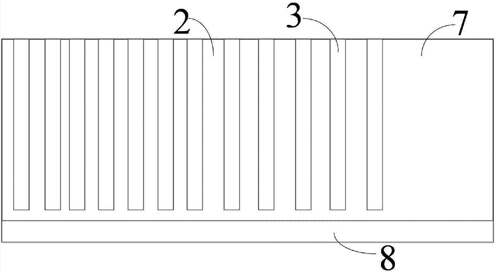
[0040] Such as figure 1As shown: taking an N-type MOSFET device as an example, the present invention includes a semiconductor substrate having two opposite main surfaces, the two opposite main surfaces include a first main surface and a second main surface corresponding to the first main surface, There is an N+ substrate 8 and an N-type epitaxial layer 7 between the first main surface and the second main surface, the N-type epitaxial layer 7 is located above the N+ substrate 8, and the N-type epitaxial layer 7 is adjacent to the N+ substrate 8;

[0041] A terminal superjunction is provided in the terminal region of the N-type epitaxial layer 7, and the terminal superjunction includes a P-type main junction 1 and several alternately distributed N columns 2 and P columns 3;

[0042] The width of the N-column 2 increases gradually along the direction from the P-t...


PUM


Abstract

The invention relates to a super junction terminal structure and a preparation method thereof. A terminal super junction comprises a second conductivity type main junction, and a plurality of first conductivity type pillars and second conductivity type pillars distributed alternately. The width of the first conductivity type pillars gradually increases from the second conductivity type main junction to the edge direction of a terminal area. The outer circle of the second conductivity type main junction is provided with at least one second conductivity type field limiting ring. Each second conductivity type field limiting ring is on the top of one second conductivity type pillar in a first conductivity type epitaxial layer. A field plate is arranged on each second conductivity type field limiting ring, and the field plate covers the second conductivity type field limiting ring and a protective layer laterally above the second conductivity type field limiting ring. The protective layers are arranged on a first main surface. The super junction terminal structure is compact and compatible with the prior art. Under the condition of meeting the withstand voltage, the chip area is saved, and the process cost is reduced. The super junction terminal structure is safe and reliable.

Description

technical field [0001] The invention relates to a terminal structure, in particular to a super junction terminal structure and a preparation method thereof, belonging to the technical field of semiconductor devices. Background technique [0002] The super junction field effect transistor is a new type of MOSFET device. The SJ (Superjunction, super junction)-MOSFET device is different from the traditional MOSFET device. Its drift region is composed of N and P alternating vertical columns. When withstand voltage, The mutual depletion of the N-pillar and the P-pillar forms a charge compensation effect. By introducing a transverse electric field, the distribution of the longitudinal electric field in the drift region is as uniform and gentle as possible to increase the breakdown voltage. The superjunction structure is due to Due to the high doping concentration in the drift region, the conventional terminal structure no longer meets the requirements, and a matching superjunction...

Claims


Application Information

Patent Timeline
Patent Type & Authority Applications(China)
IPC IPC(8): H01L29/06H01L29/78H01L21/336
CPCH01L29/7827H01L29/0634H01L29/66666
Inventor 张广银朱阳军
Owner 江苏芯长征微电子集团股份有限公司
Learn More