Fertilizer applicator

The technology of a fertilizer applicator and a fertilizer applicator is applied in the directions of a fertilizer applicator, a planting method, a fertilizer distributor, etc., which can solve the problems of uneven fertilizer application, damage to the root system of plants, low efficiency, etc., so as to improve the effect of fertilizer application, reduce labor intensity and work efficiency. high effect

Inactive Publication Date: 2017-08-29
河南颇文商贸有限公司
View PDF8 Cites 8 Cited by
  • Summary
  • Abstract
  • Description
  • Claims
  • Application Information

AI Technical Summary

Problems solved by technology

[0002] At present, agricultural fertilization generally adopts manual trenching and fertilization, which needs to carry heavy equipment for storing chemical fertilizers or farmyard manure, and then fertilizes a little bit on the side of the plants. After fertilization, it needs to be manually covered with soil. Underneath, fertilization is uneven, and the fertilization effect is directly affected by the depth of fertilization; the current method of mechanical furrowing and fertilization will cause certain damage to the root system of the plant, not only making the fertilizer applied in the furrow unable to be fully absorbed by the roots of the fruit trees, resulting in waste of fertilizer, Moreover, the balance between water absorption and transpiration by the root system will also be destroyed, which is not conducive to the growth of plants, and it does not have the function of covering soil, so it still needs to be covered separately.
At the same time, the existing fertilization machine is to mix the fertilizers together, and the two fertilization tanks are arranged left and right, which cannot be used for the conventional fertilization method of farmyard manure and chemical fertilizer fertilization at intervals

Method used


Image

  • Fertilizer applicator
  • Fertilizer applicator
  • Fertilizer applicator

Examples


Embodiment Construction

[0024] The present invention will be further described below in conjunction with embodiment.

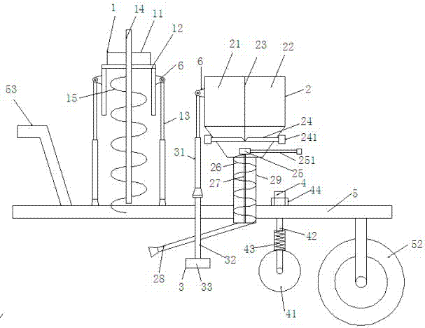
[0025] A fertilizer applicator such as figure 1 Shown, comprise frame 5, one end of described frame 5 is provided with traction frame 53, and the other end is provided with traveling wheel 52, and described frame 5 is provided with fertilizing device 2; Described fertilizing machine also comprises digging device 1 and a soil covering device 3; the soil covering device 3 is arranged between the digging device 1 and the fertilization device 2;

[0026] The digging device 1 includes a digging device outer frame 12, and the digging device outer frame 12 is provided with a digging shaft 14 and a helical tooth 15. When the digging shaft 14 rotates, it can drive the helical tooth 15 to rotate, so The end of the digging rotating shaft 14 is connected with a digging motor 11, and the upper end of the outer wall of the digging device outer frame 12 is connected with a vertical digging lifting...


PUM


Abstract

The invention provides a fertilizer applicator comprising a frame, the front end of the frame is provided with a traction frame, the back end of the frame is provided with a walking wheel, a fertilizing device, a hole digging device and a soil covering device are arranged on the frame, the hole digging device comprises a hole digging device outer frame, a hole digging rotating shaft and a helical tooth are arranged in the hole digging device outer frame, the outer side wall of the hole digging device outer frame is connected with a hole digging lifting oil cylinder, the lower end of the hole digging lifting oil cylinder is fixed on the frame, and the lower end of the side wall of the hole digging device outer frame is hung above the frame; the fertilizing device includes a chemical fertilizer storage tank and a farm manure storage tank which are separated by a separator; a fertilizing control board is arranged between the side wall of the chemical fertilizer storage tank and the separator, the fertilizing control board is a scalable plate, one end of the scalable plate is fixed at the external of a fertilizer storage tank, and is connected with a fertilizing control oil cylinder, the lower part of the fertilizer storage tank is connected with a stirring tank, and the lower end of the stirring tank is connected with a fertilizer conveying pipe. The fertilizer applicator integrates the functions of hole digging, fertilizing and soil covering soil, and realizes the interval fertilization of a farmyard manure and a chemical fertilizer.

Description

technical field [0001] The invention relates to the technical field of agricultural machinery, in particular to a fertilizer applicator. Background technique [0002] At present, agricultural fertilization generally adopts manual trenching and fertilization, which needs to carry heavy equipment for storing chemical fertilizers or farmyard manure, and then fertilizes a little bit on the side of the plants. After fertilization, it needs to be manually covered with soil. Underneath, fertilization is uneven, and the effect of fertilization is directly affected by the depth of fertilization; the current method of mechanical furrowing and fertilization will cause certain damage to the root system of the plant, not only making the fertilizer applied in the furrow unable to be fully absorbed by the roots of the fruit trees, resulting in waste of fertilizer, Moreover, the balance relationship between root system absorption of water and transpiration will also be destroyed, which is u...

Claims


Application Information

Patent Timeline
Patent Type & Authority Applications(China)
IPC IPC(8): A01C15/12A01C15/00A01C5/04
CPCA01C15/124A01C5/04A01C15/005
Inventor 向晓霞
Owner 河南颇文商贸有限公司
Why Eureka
Try Eureka