
Ultra-short closure section of rotation construction bridge and construction method thereof

A closing section and swivel technology, which is applied in bridges, bridge construction, erection/assembly of bridges, etc., can solve problems such as the impact on the operation of existing buildings, the difficulty of ensuring safety, and the complicated construction process of the post-casting closing section, etc., to achieve Easy to adjust deviation correction, reduce construction risk, and solve the effect of overturning problems

Active Publication Date: 2017-08-29
CHINA RAILWAY SIYUAN SURVEY & DESIGN GRP
View PDF16 Cites 5 Cited by
  • Summary
  • Abstract
  • Description
  • Claims
  • Application Information

AI Technical Summary

Problems solved by technology

[0002]Conventional continuous beams need to be closed by swivel during construction. Since the end faces of the swivel beams at both ends are the same as ordinary rectangular sections, in order to prevent mutual Interference, the reserved post-casting closing gap is wide, which makes the construction process of the post-casting closing section complicated
At present, the construction method of cast-in-situ or segmented cantilever pouring is usually adopted at the bridge position. If the bridge spans important buildings, such as high-speed railways, it will inevitably have a great impact on the operation of existing buildings, and it is difficult to guarantee safety.

Method used


Image

  • Ultra-short closure section of rotation construction bridge and construction method thereof
  • Ultra-short closure section of rotation construction bridge and construction method thereof
  • Ultra-short closure section of rotation construction bridge and construction method thereof

Examples


Embodiment Construction

[0026] Below in conjunction with accompanying drawing and specific embodiment the present invention is described in further detail:

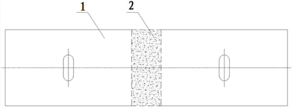
[0027] like figure 1 As shown, there is a large post-cast closing gap between the two sections of the swivel beam body 1 of the traditional swivel construction bridge, resulting in a large width of the closing section 2, and the construction process of the post-casting closing section is complicated.

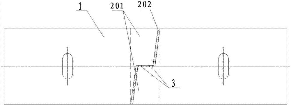
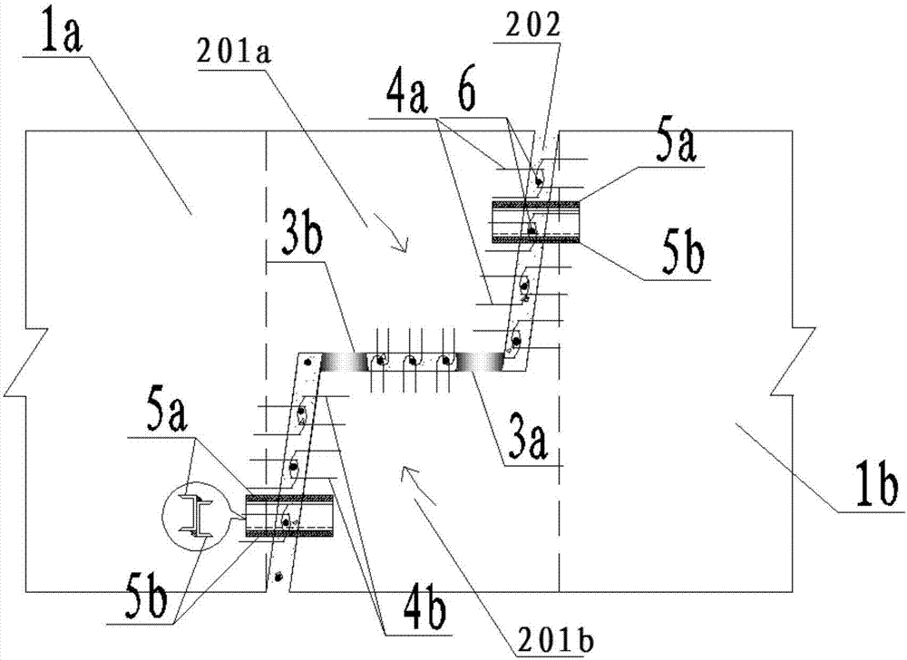
[0028] like figure 2 and 3 As shown, the closing section of the present invention is composed of a pouring closing section 201 and a post-casting closing section 202. In order to prevent the two sections of swivel beams from interfering with each other during the rotation process, the first pouring closing section 201 is divided into two sections along the longitudinal axis of the bridge. Left half 201a and right half 201b. The two sections of swivel beams 1 are respectively a first swivel beam 1a and a second swivel beam 1b, the end of the fi...


PUM


Abstract

The invention relates to the technical field of construction of continuous beams, in particular to an ultra-short closure section of a rotation construction bridge and a construction method thereof. The ultra-short closure section of the rotation construction bridge comprises a first rotation beam body, a second rotation beam body and a closure section body, wherein the first rotation beam body is connected with the second rotation beam body by the closure section body; the closure section body comprises a pre-pouring closure section body and a post-pouring closure section body; the pre-pouring closure section body is divided into a left half part and a right half part along the longitudinal axis of the bridge; an end of the first rotation beam body is fixedly connected with one end of the left half part; an end of the second rotation beam body is fixedly connected with one end of the right half part; after the first rotation beam body and the second rotation beam body rotate and are closed, a post-pouring closure gap is formed; the post-pouring closure section body is arranged in the post-pouring closure gap; and the left half part, the right half part, the first rotation beam body and the second rotation beam body are connected to form a whole continuous beam. A folding hanging bracket is not required, construction at the present stage can be finished by a simple template, steel is saved, the cost is low, and the construction time of the closure section is shortened to a great extent.

Description

technical field [0001] The invention relates to the technical field of continuous beam construction, in particular to an ultra-short closure section of a swivel construction bridge and a construction method thereof. Background technique [0002] Conventional continuous beams need to be closed by swivel during construction. Since the end faces of the swivel beams at both ends are ordinary rectangular sections, in order not to interfere with each other during the swivel, the reserved post-cast closing gap is wide, resulting in post-cast The construction process of the closing section is complicated. At present, the construction method of cast-in-situ or segmented cantilever pouring is usually adopted at the bridge position. If the bridge spans important buildings, such as high-speed railways, it will inevitably have a great impact on the operation of existing buildings, and it is difficult to guarantee safety. . In order to reduce the interference of existing roads or high-s...

Claims


Application Information

Patent Timeline
Patent Type & Authority Applications(China)
IPC IPC(8): E01D21/08
CPCE01D21/08
Inventor 柏华军毕玉琢王德志文望青李海泉柳鸣
Owner CHINA RAILWAY SIYUAN SURVEY & DESIGN GRP
Learn More