
Local reinforcing equipment and method for wind power generator unit foundation ring

A wind power generation unit, local reinforcement technology, applied in the direction of wind power generation, infrastructure engineering, foundation structure repair, etc., can solve problems such as not taking into account the gap between the foundation ring and concrete, and the increase of the gap between the foundation ring and concrete, etc., Achieve the effects of increasing service life, slowing down fatigue damage, and avoiding welding stress and deformation

Active Publication Date: 2017-08-29
HUNAN UNIV OF SCI & TECH
View PDF7 Cites 13 Cited by
  • Summary
  • Abstract
  • Description
  • Claims
  • Application Information

AI Technical Summary

Problems solved by technology

[0003] The traditional wind turbine foundation reinforcement system only uses the method of injecting high-strength grouting material or epoxy resin glue into the gap for the local cracking and crushing of the surface concrete of the wind turbine foundation, which causes the cracks between the foundation ring and the concrete to increase. , although the cured high-strength grouting material or epoxy resin glue can fill the resulting cracks, but this method does not take into account that the cracks between the foundation ring and the concrete are caused by the vibration of the foundation ring caused by the long-term wind load on the upper part of the wind turbine , no reasonable measures have been taken in the structure to effectively disperse the stress transmitted from the upper load to the foundation ring, thereby slowing down the generation and expansion of concrete cracks. Therefore, with traditional reinforcement systems, the phenomenon of concrete cracks will still exist, and wind power generation will be maintained after reinforcement. The normal operation time of the machine will not be very long

Method used


Image

  • Local reinforcing equipment and method for wind power generator unit foundation ring
  • Local reinforcing equipment and method for wind power generator unit foundation ring
  • Local reinforcing equipment and method for wind power generator unit foundation ring

Examples


Embodiment Construction

[0032] The present invention will be further described below in conjunction with the accompanying drawings and embodiments.

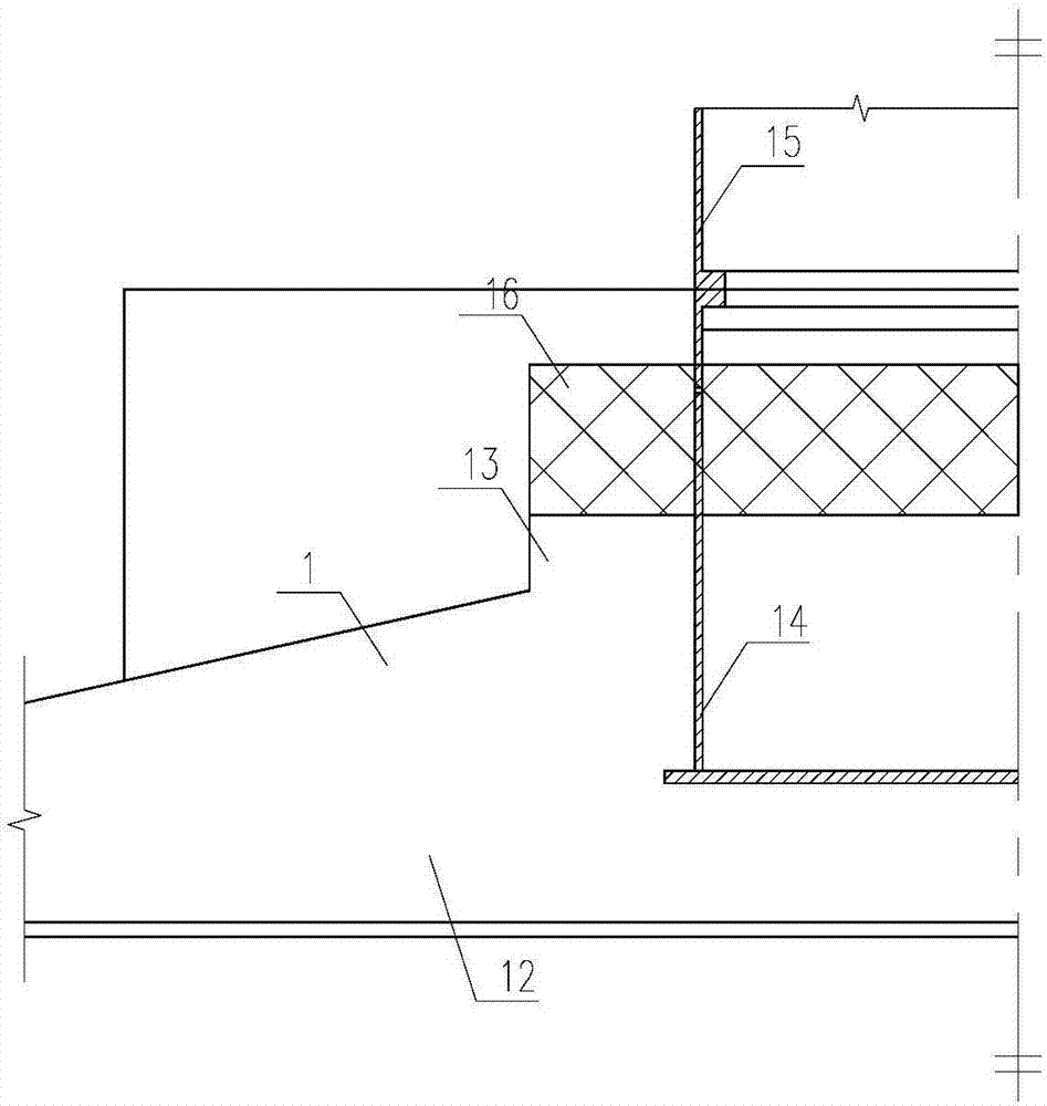
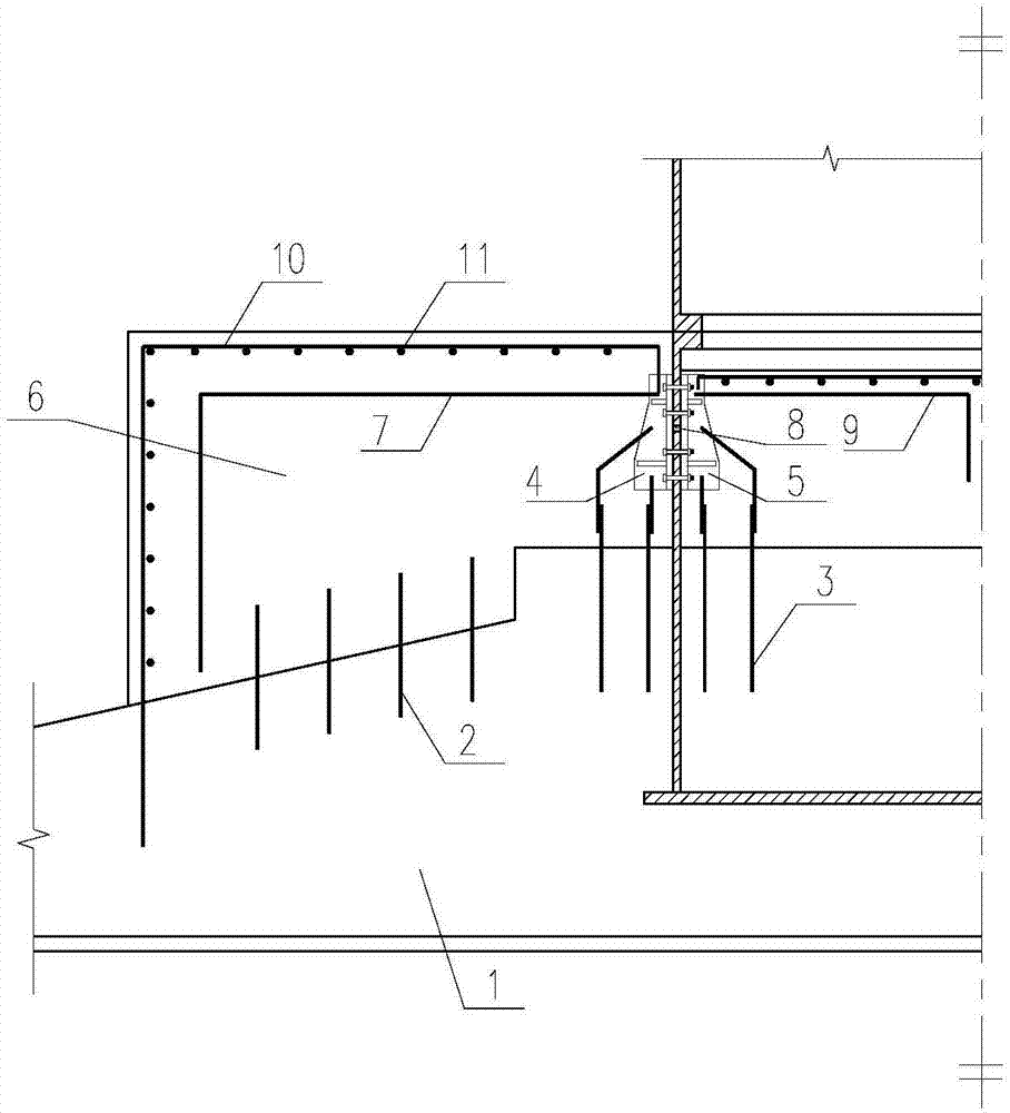
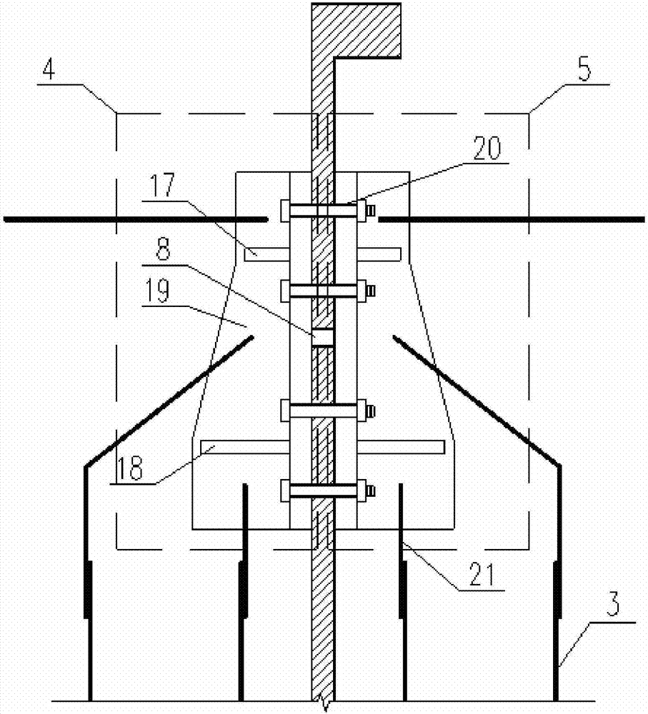
[0033] Such as figure 2 As shown, a local reinforcement device for the foundation ring of a wind power generating set includes an original reinforced concrete foundation 1 and a local reinforcement device; the original reinforced concrete foundation 1 includes a base plate 12, a pier 13 and a base ring 14, and the base plate 12 is embedded in the ground , the middle part of the foundation bottom plate 12 is provided with a pier 13, the foundation ring 14 is embedded in the pier 13, the top of the foundation ring 14 is connected with the tower tube 15, and the part of the foundation bottom plate 12 located outside the pier 13 is vertically provided with a plurality of insertion ribs 2 , the local reinforcement device includes a newly poured reinforced concrete foundation 6, an inner steel splint unit 5, and an outer steel splint unit 4, and a plurality ...


PUM


Abstract

The invention discloses local reinforcing equipment for a wind power generator unit foundation ring. The local reinforcing equipment comprises an original reinforced concrete foundation and a local reinforcing device. The local reinforcing device comprises a newly-poured reinforced concrete foundation, inner side steel clamping plate units and outer side steel clamping plate units. The multiple inner side steel clamping plate units are arranged on the inner wall of the upper portion of a foundation ring of the original reinforced concrete foundation in an annular mode, and the multiple outer side steel clamping plate units are arranged on the outer wall of the upper portion of the foundation ring in an annular mode; and the newly-poured reinforced concrete foundation is poured on the original reinforced concrete foundation. According to the local reinforcing equipment for the wind power generator unit foundation ring, loads which are borne by the foundation ring and generated by a draught fan in a running state are dispersedly transmitted through the inner side steel clamping plate units, the outer side steel clamping plate units, connecting steel bars, inner foundation negative bend steel bars and outer foundation negative bend steel bars, stress in the reinforced foundation ring is effectively reduced, fatigue damage to a draught fan foundation is reduced, and the service life period of the reinforced draught fan foundation is greatly prolonged. The invention further discloses a local reinforcing method for the wind power generator unit foundation ring.

Description

technical field [0001] The invention relates to the field of wind power, in particular to a local reinforcement device and method for a foundation ring of a wind power generating set. Background technique [0002] In recent years, in the field of power generation in my country, wind power projects have developed rapidly, and the construction of onshore wind power generating units has greatly increased. However, after the generating units are completed, engineering quality accidents occur from time to time. It has been tested and verified that the cause of most engineering accidents is that during the construction process, the quality control of the surface concrete near the fan base ring is not good enough, the actual strength of the concrete is lower than the design strength, and the fan has been vibrating under the wind load for a long time. The nearby concrete is constantly contacted and squeezed, especially the concrete near the foundation ring in the main wind direction...

Claims


Application Information

Patent Timeline
Patent Type & Authority Applications(China)
IPC IPC(8): E02D27/44E02D27/42E02D37/00
CPCE02D27/425E02D27/44E02D37/00Y02E10/728
Inventor 卢倍嵘吕伟荣彭柱何潇锟丁时宝祝明桥胡益民朱峰冯高煜
Owner HUNAN UNIV OF SCI & TECH
Learn More