Cement transportation discharging device for urban building ditch

A ditch and building technology, used in buildings, waterway systems, water supply devices, etc., can solve the problems of time-consuming and labor-intensive, low labor efficiency, etc.

Inactive Publication Date: 2017-08-29
宜昌鼎燊建设工程有限公司
View PDF4 Cites 2 Cited by
  • Summary
  • Abstract
  • Description
  • Claims
  • Application Information

AI Technical Summary

Problems solved by technology

[0007] In order to overcome the shortcomings of low labor efficiency and time-consuming and labor-intensive work process when the cement is transported and unloaded in the ditches of urban buildings, the technical problem to be solved by the present invention is to provide equipment with high work efficiency and low work process. A time-saving and labor-saving cement transportation and cutting equipment for urban construction ditches

Method used


Image

  • Cement transportation discharging device for urban building ditch
  • Cement transportation discharging device for urban building ditch
  • Cement transportation discharging device for urban building ditch

Examples


Embodiment 1

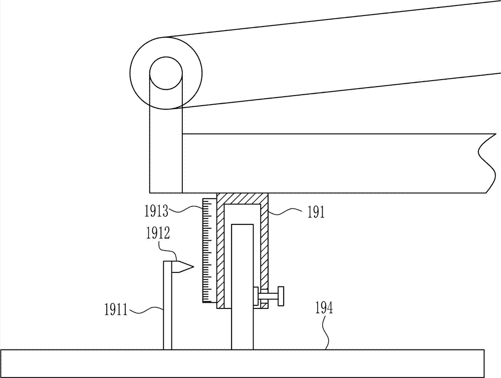
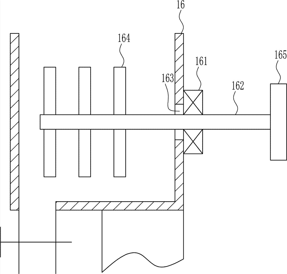
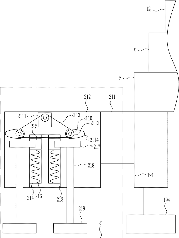
[0039] A cement transportation and cutting equipment for urban building ditches, such as Figure 1-8 As shown, it includes a mounting plate 1, a first supporting seat 2, a first rotating shaft 3, a tire 4, a first connecting rod 5, a second supporting seat 6, a second rotating shaft 7, a supporting plate 8, a third supporting seat 9, The third rotating shaft 10, the first runner 11, the conveyor belt 12, the first motor 13, the second runner 14, the first drive bar 15, the cement tank 16, the feeding pipe 17 and the valve 18, the left and right sides of the lower side of the mounting plate 1 The first supporting base 2 is installed on both sides by welding, the first rotating shaft 3 is rotatably connected to the inner side of the first supporting base 2, the tire 4 is connected to the first rotating shaft 3, and the left end of the mounting plate 1 is installed by welding. The first connecting rod 5, the left end of the first connecting rod 5 is installed with the second supp...

Embodiment 2

[0041] A cement transportation and cutting equipment for urban building ditches, such as Figure 1-8As shown, it includes a mounting plate 1, a first supporting seat 2, a first rotating shaft 3, a tire 4, a first connecting rod 5, a second supporting seat 6, a second rotating shaft 7, a supporting plate 8, a third supporting seat 9, The third rotating shaft 10, the first runner 11, the conveyor belt 12, the first motor 13, the second runner 14, the first drive bar 15, the cement tank 16, the feeding pipe 17 and the valve 18, the left and right sides of the lower side of the mounting plate 1 The first supporting base 2 is installed on both sides by welding, the first rotating shaft 3 is rotatably connected to the inner side of the first supporting base 2, the tire 4 is connected to the first rotating shaft 3, and the left end of the mounting plate 1 is installed by welding. The first connecting rod 5, the left end of the first connecting rod 5 is installed with the second suppo...

Embodiment 3

[0044] A cement transportation and cutting equipment for urban building ditches, such as Figure 1-8 As shown, it includes a mounting plate 1, a first supporting seat 2, a first rotating shaft 3, a tire 4, a first connecting rod 5, a second supporting seat 6, a second rotating shaft 7, a supporting plate 8, a third supporting seat 9, The third rotating shaft 10, the first runner 11, the conveyor belt 12, the first motor 13, the second runner 14, the first drive bar 15, the cement tank 16, the feeding pipe 17 and the valve 18, the left and right sides of the lower side of the mounting plate 1 The first supporting base 2 is installed on both sides by welding, the first rotating shaft 3 is rotatably connected to the inner side of the first supporting base 2, the tire 4 is connected to the first rotating shaft 3, and the left end of the mounting plate 1 is installed by welding. The first connecting rod 5, the left end of the first connecting rod 5 is installed with the second supp...


PUM


Abstract

The invention relates to a cement discharging device, in particular to a cement transportation discharging device for an urban building ditch. The cement transportation discharging device for the urban building ditch achieves the technical purposes that the adopted device is high in working efficiency, and time and labor are saved in the working process. In order to achieve the technical purposes, the cement transportation discharging device for the urban building ditch comprises an installation plate, first supporting bases, first rotating shafts, tires, a first connecting rod, a second supporting base, a second rotating shaft, a supporting plate, a third supporting base, a third rotating shaft and the like; the left and right sides of the lower side of the installation plate are provided with the first supporting bases in a welded mode, the first rotating shafts are connected to the portions below the inner sides of the first supporting bases in a rotating mode, and the tires are connected to the first rotating shafts. The cement transportation discharging device achieves the effects that the adopted device is high in working efficiency and time and labor are saved in the working process, and the mode that discharging and cement stirring are performed at the same time is adopted.

Description

technical field [0001] The invention relates to a cement cutting equipment, in particular to a cement transportation and cutting equipment for urban building ditches. Background technique [0002] Ditches can be roughly divided into two types. One is the rainwater sewer that can be seen everywhere on the roadside, and the other is the sewage sewer that transports the wastewater from homes and factories to the sewage treatment plant in a closed pipeline. [0003] Cement: powdery hydraulic inorganic gelling material. After adding water and stirring, it becomes a slurry, which can be hardened in the air or better hardened in water, and can firmly bind sand, stone and other materials together. In the early years the mixture of lime and volcanic ash is very similar to lime pozzolanic cement, use it to glue concrete which made of crushed stone. After hardening, the cement not only has high strength, but also can resist the erosion of fresh water or salt water. For a long time, ...

Claims


Application Information

Patent Timeline
IPC IPC(8): E03F3/06
CPCE03F3/06
Inventor 不公告发明人
Owner 宜昌鼎燊建设工程有限公司
Why Eureka
Try Eureka