

Right angle calibration block layout method, coordinate calibration method and coordinate adjusting method for gear measurement center
A technology of gear measurement and layout method, which is applied in the direction of point coordinate measurement, electromagnetic measurement device, etc., to achieve the effect of ensuring accuracy, simple structure, and not affecting the measurement.
- Summary
- Abstract
- Description
- Claims
- Application Information
AI Technical Summary
Problems solved by technology
Method used
Image

Examples
Embodiment Construction
[0054] The specific embodiment of the present invention is described in detail below in conjunction with each accompanying drawing:
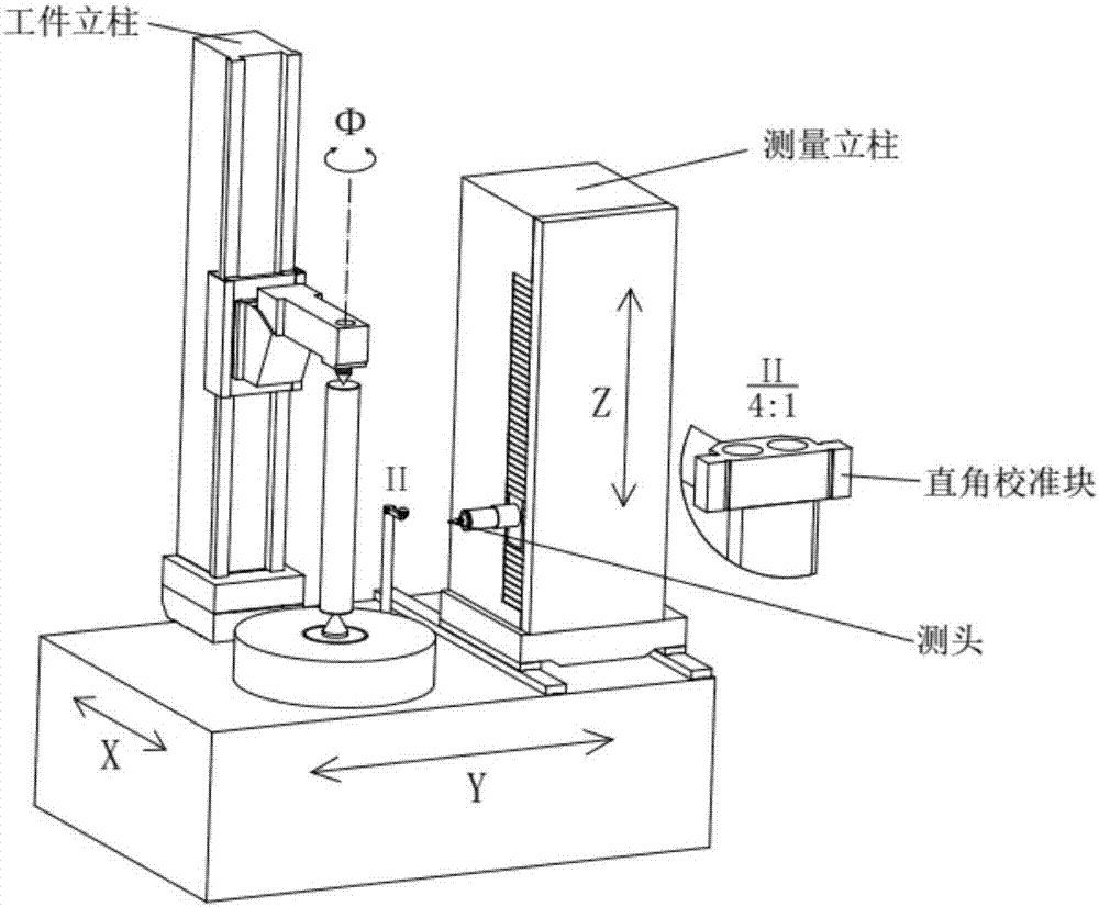
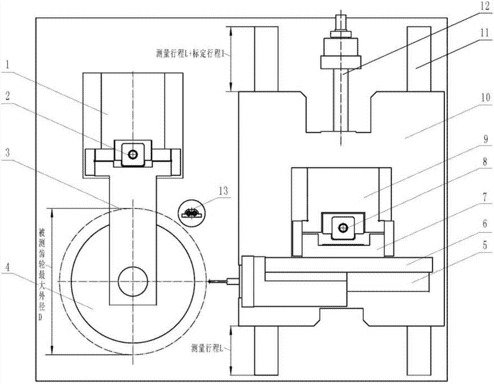
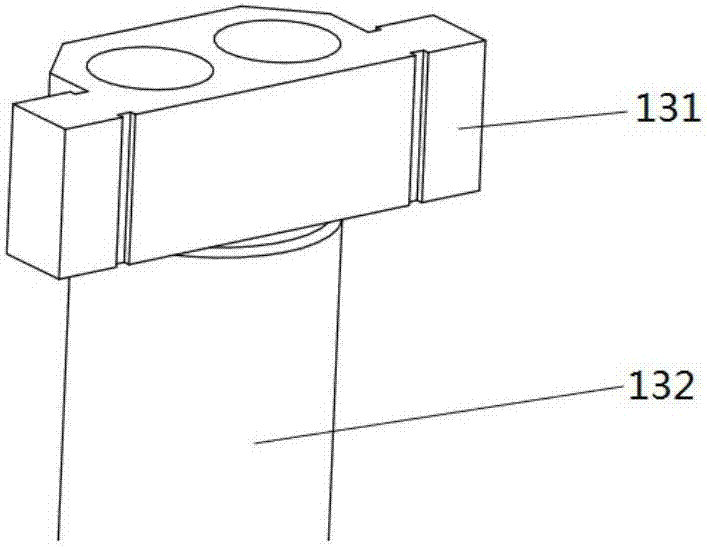
[0055] The layout method of the right angle calibration block in the gear measurement center of the present invention, refer to figure 2 and image 3 , the right-angle calibration block is fixedly installed on the base of the gear measurement center at a position other than the measurement stroke, and the tangential X coordinate axis guide rail stroke of the gear measurement center adopts a front-to-back asymmetric layout. The characteristics of this layout are for Before the instrument is measured, the probe moves to the right-angle calibration block to complete the probe calibration process of the instrument without affecting the scope of use of the instrument;
[0056] On the basis of the structural layout of the above-mentioned right-angle calibration block in the gear measurement center, the present invention further provides a coordinate...
PUM
 Abstract
Description
Claims
Application Information