An automatic avoidance method for the testing axis of a flying probe testing machine

A flying probe testing machine and automatic avoidance technology, applied in the direction of electronic circuit testing, measuring electricity, measuring devices, etc., can solve problems such as customer loss, and achieve the effect of avoiding collision, avoiding the method is simple, and easy to achieve

Active Publication Date: 2020-01-07
HANS CNC SCI & TECH
View PDF3 Cites 0 Cited by
  • Summary
  • Abstract
  • Description
  • Claims
  • Application Information

AI Technical Summary

Problems solved by technology

However, in the existing technology, due to the allocation of test points, the test axis will inevitably collide during high-speed motion, which will inevitably bring losses to customers

Method used


Image

  • An automatic avoidance method for the testing axis of a flying probe testing machine
  • An automatic avoidance method for the testing axis of a flying probe testing machine
  • An automatic avoidance method for the testing axis of a flying probe testing machine

Examples


Embodiment Construction

[0036] In order to facilitate the understanding of the present invention, the present invention will be described more fully below with reference to the associated drawings. Preferred embodiments of the invention are shown in the accompanying drawings. However, the present invention can be embodied in many different forms and is not limited to the embodiments described herein. On the contrary, these embodiments are provided to make the understanding of the disclosure of the present invention more thorough and comprehensive.

[0037] Unless otherwise defined, all technical and scientific terms used herein have the same meaning as commonly understood by one of ordinary skill in the technical field of the invention. The terms used herein in the description of the present invention are for the purpose of describing specific embodiments only, and are not intended to limit the present invention.

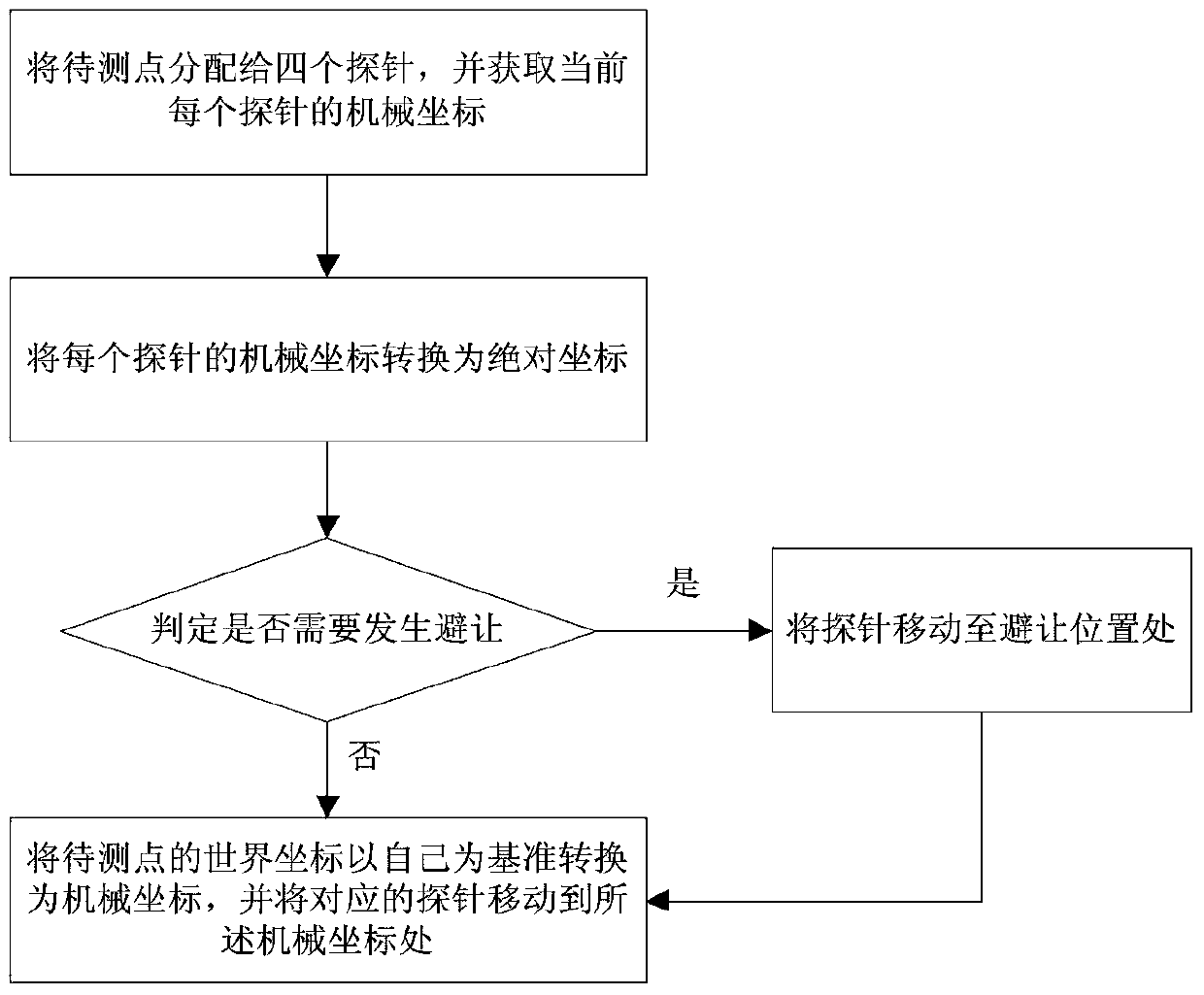
[0038] refer to figure 1 As shown, the present invention provides an automatic avoi...


PUM


Abstract

The invention relates to the technical field of circuit board test equipment, and discloses a flying probe tester test shaft automatic avoidance method. The front surface of a flying probe tester is provided with probes Tip 1 and Tip 2 and the reverse surface is provided with probes Tip 3 and Tip 4. According to the automatic avoidance method, firstly points to be tested are allocated to the four probes Tip 1, Tip 2, Tip 3 and Tip 4 and the current mechanical coordinates of each probe are acquired; the mechanical coordinates of each probe are transformed into absolute coordinates, wherein the probes Tip 1 and Tip 2 are based on the probe Tip 1 in the transformation process, and the probes Tip 3 and Tip 4 are based on the probe Tip 3; avoidance is judged through the position relation of the world coordinates of the current measurement points corresponding to the two probes of the same side and the points to be tested, and one of the probes is moved to the avoidance position if avoidance is required; and if avoidance is not required, the world coordinates of the points to be tested are directly transformed into the mechanical coordinates based on themselves and the corresponding probes are moved to the positions of the mechanical coordinates. The method is simple, reliable and easy to implement.

Description

technical field [0001] The invention relates to the technical field of circuit board testing equipment, and more specifically relates to an automatic avoidance method for a testing axis of a flying probe testing machine. Background technique [0002] The flying probe testing machine is an improved instrument for the traditional needle bed online tester. It can replace the needle bed with probes. The X-Y mechanism is equipped with 4 test probes that can move at high speed respectively. During operation, the unit under test is transported into the testing machine through a belt or other conveying system, and then the probes of the fixed testing machine touch the test pad and the via hole, thereby testing a single component of the unit under test. [0003] The flying probe testing machine uses probes to replace the needle bed, and uses multiple motor-driven, fast-moving electrical probes to make contact with the pins of the device and perform electrical measurements. [0004] ...

Claims


Application Information

Patent Timeline
Patent Type & Authority Patents(China)
IPC IPC(8): G01R31/28
CPCG01R31/2818
Inventor 张恂欧阳云轩王星翟学涛杨朝辉高云峰
Owner HANS CNC SCI & TECH
Why Eureka
Try Eureka