Check patentability & draft patents in minutes with Patsnap Eureka AI!

Symbol detection circuit and method

A detection circuit and detection method technology, which is applied in the direction of television, electrical components, image communication, etc., can solve the problems that the filter 340 has a long filtering time and cannot completely filter out continuous wave interference, and achieves filtering of continuous wave interference and short filter the effect of time

Inactive Publication Date: 2017-08-29
MSTAR SEMICON INC
View PDF6 Cites 0 Cited by
  • Summary
  • Abstract
  • Description
  • Claims
  • Application Information

AI Technical Summary

Problems solved by technology

However, this will cause the filtering time of the filter 340 to be longer; on the contrary, if the filter 340 adopts a shorter window length (such as 482T or 542T), although the correlation value can be obtained quickly, the continuous wave interference cannot be completely filtered out.
Such limitations force known circuits to make a trade-off between detection speed and accuracy

Method used


Image

  • Symbol detection circuit and method
  • Symbol detection circuit and method
  • Symbol detection circuit and method

Examples


Embodiment Construction

[0044] The disclosure content of the present invention includes the symbol detection circuit and method. On the premise that the implementation is possible, those skilled in the art can select equivalent components or steps to realize the present invention according to the disclosure content of this specification, that is, the Implementation is not limited to the examples described below.

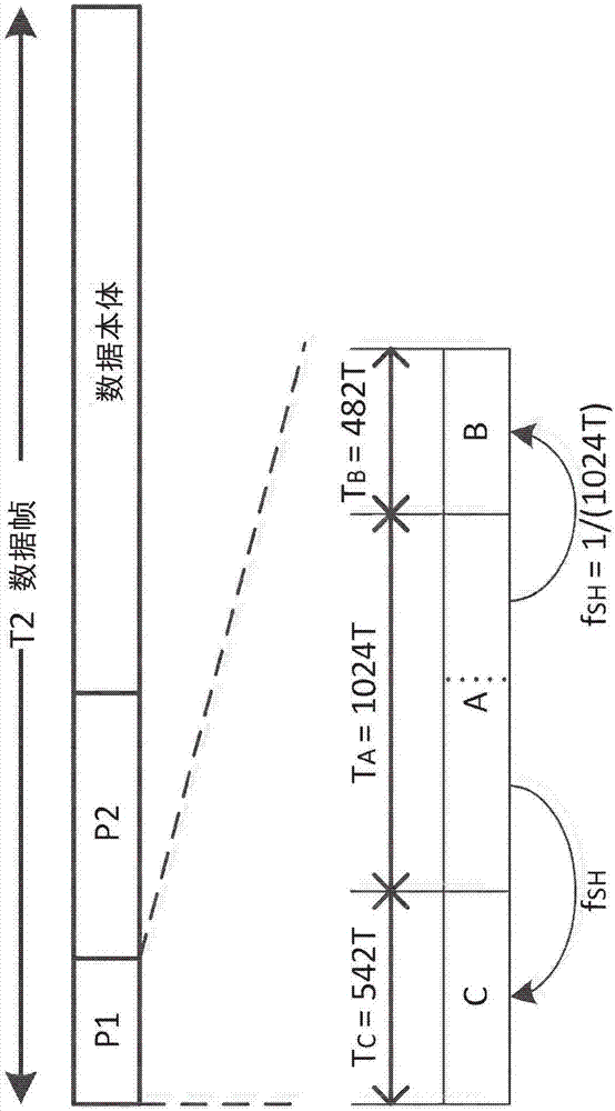
[0045] Assume that the input signal X[n] of the DVB-T2 receiver is expressed as follows:

[0046] X[n]=P 1 [n-θ]·exp(j2πΦnT S )+exp(j2πf CW n S ) (1)

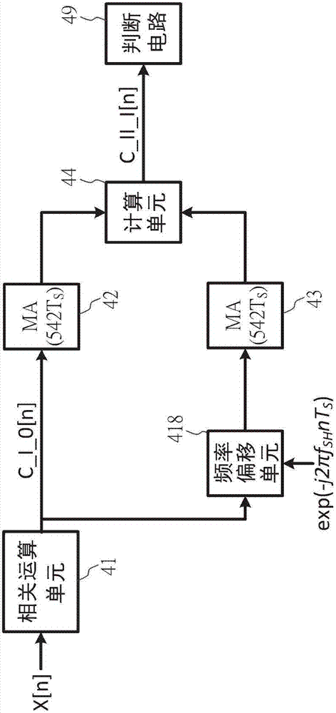
[0047] where P 1 [n-θ]·exp(j2πΦnTS ) is the part of the P1 symbol, θ represents the sampling delay, Φ is the carrier frequency offset; exp(j2πf CW n S ) is a single-tone continuous wave interference (frequency f CW ). For ease of illustration, channel effects and noise are ignored here. Delay X[n] by T C (that is, the length of the delayed data C, 542 samples), and then multiplied by its own conjugate, the signal C_I_0[n] can be o...


PUM


Abstract

The present invention provides a detection method applied to the receiving end of a digital video broadcast and used for detecting the position of one data frame of an input signal. The input signal comprises a continuous wave interference component. The method comprises the steps of generating a correlation signal according to the input signal; subjecting the correlation signal to moving average calculation to generate a first moving average result; subjecting the correlation signal to the frequency offset treatment to generate a correlation signal after the frequency offset treatment; subjecting the correlation signal after the frequency offset treatment to the moving average calculation to generate a second moving average result; according to the first moving average result and the second moving average result, eliminating the continuous wave interference component, and accordingly generating an output signal; and judging the position according to the peak value of the output signal.

Description

technical field [0001] The present invention relates to a symbol detection circuit and a method, in particular to a symbol detection circuit and a method of a second generation digital video broadcasting (Digital Video Broadcasting over Terrestrial 2, hereinafter referred to as DVB-T2) system. Background technique [0002] figure 1 It is a schematic diagram of a T2 data frame (frame) of the second generation digital video broadcasting system, and each T2 data frame includes a P1 symbol, a P2 symbol and a data body. Among them, the P1 symbol carries some information of the transmitting end, such as the Fast Fourier Transform (FFT) mode used in data modulation, the digital communication system is Single Input Single Output (Single Input Single Output, hereinafter referred to as SISO) or Multiple Input Single Output (Multiple Input Single Output, hereinafter referred to as MISO) and other information. In addition to carrying the above-mentioned important information, the P1 s...

Claims


Application Information

Patent Timeline
Patent Type & Authority Applications(China)
IPC IPC(8): H04N17/00
CPCH04N17/00
Inventor 珍路易斯·朵斯赫特王堃宇赖科印童泰来廖懿颖
Owner MSTAR SEMICON INC
Features
  • R&D
  • Intellectual Property
  • Life Sciences
  • Materials
  • Tech Scout
  • Unparalleled Data Quality
  • Higher Quality Content
  • 60% Fewer Hallucinations
Learn More