
Energy supply unit and method for operating an energy supply unit for autonomously supplying a consumer

a technology for energy supply units and consumers, applied in emergency power supply arrangements, pedestrian/occupant safety arrangements, instruments, etc., can solve the problems of increasing the control output voltage due to the drop of the regulator, and achieve the effects of improving reliability, improving reliability, and improving reliability

Active Publication Date: 2015-12-03
ROBERT BOSCH GMBH
View PDF0 Cites 1 Cited by
  • Summary
  • Abstract
  • Description
  • Claims
  • Application Information

AI Technical Summary

Benefits of technology

The present invention provides a method for controlling the operation of a vehicle safety device using a monitoring signal. The monitoring signal is generated based on a combination of a reduced energy supply and a delay time between the reduced energy supply and the actual operation of the safety device. This allows for a warning to be given to the operator of the safety device in advance, increasing their operating safety. The invention is particularly useful for protecting occupants and road users in a vehicle.

Problems solved by technology

Since voltage regulators have a finite internal resistance when leaving the voltage regulating range to the downside, a regulator output current reduction in this range results in an increase in the control output voltage due a decreasing regulator drop.

Method used


Image

  • Energy supply unit and method for operating an energy supply unit for autonomously supplying a consumer
  • Energy supply unit and method for operating an energy supply unit for autonomously supplying a consumer
  • Energy supply unit and method for operating an energy supply unit for autonomously supplying a consumer

Examples


Embodiment Construction

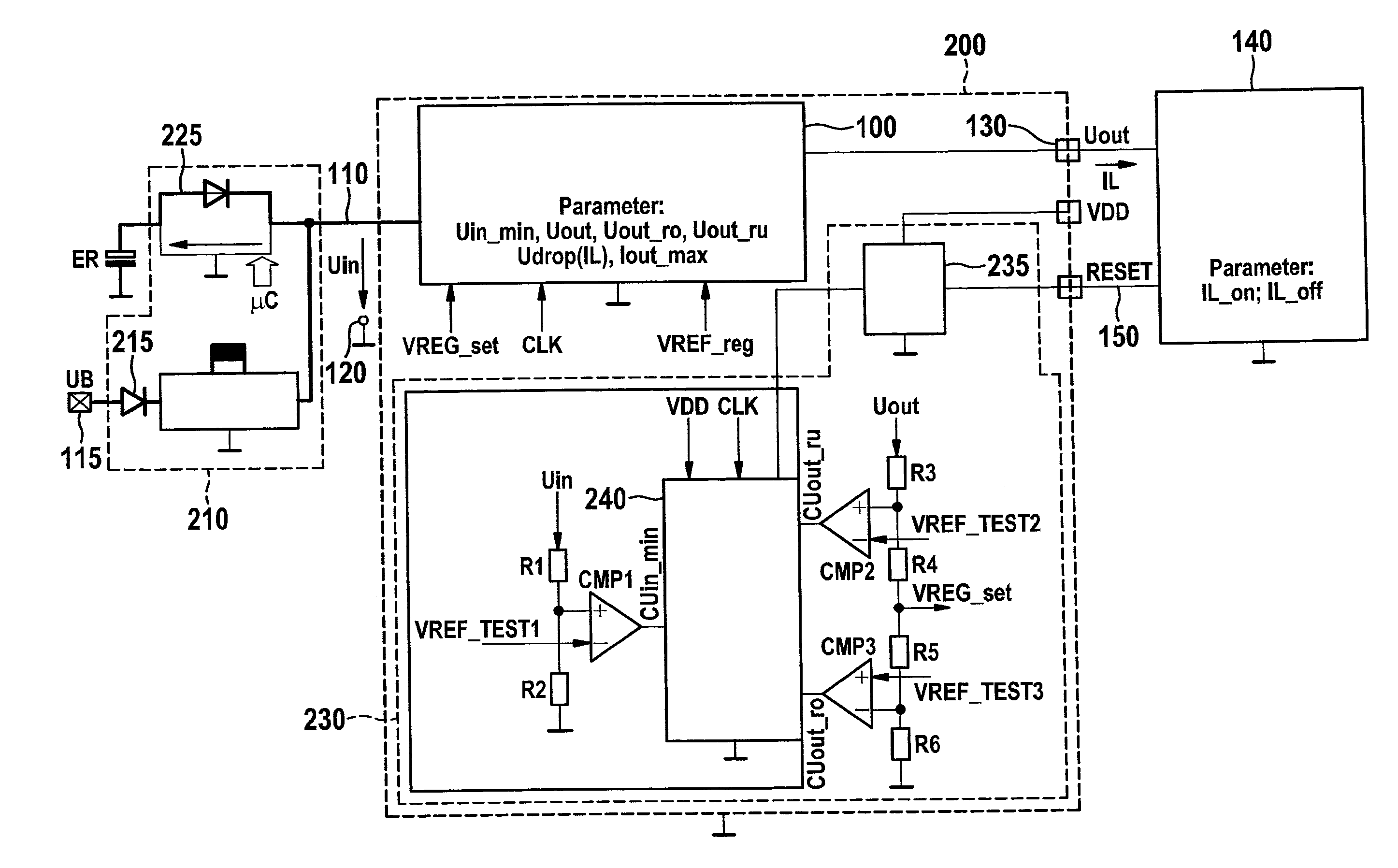
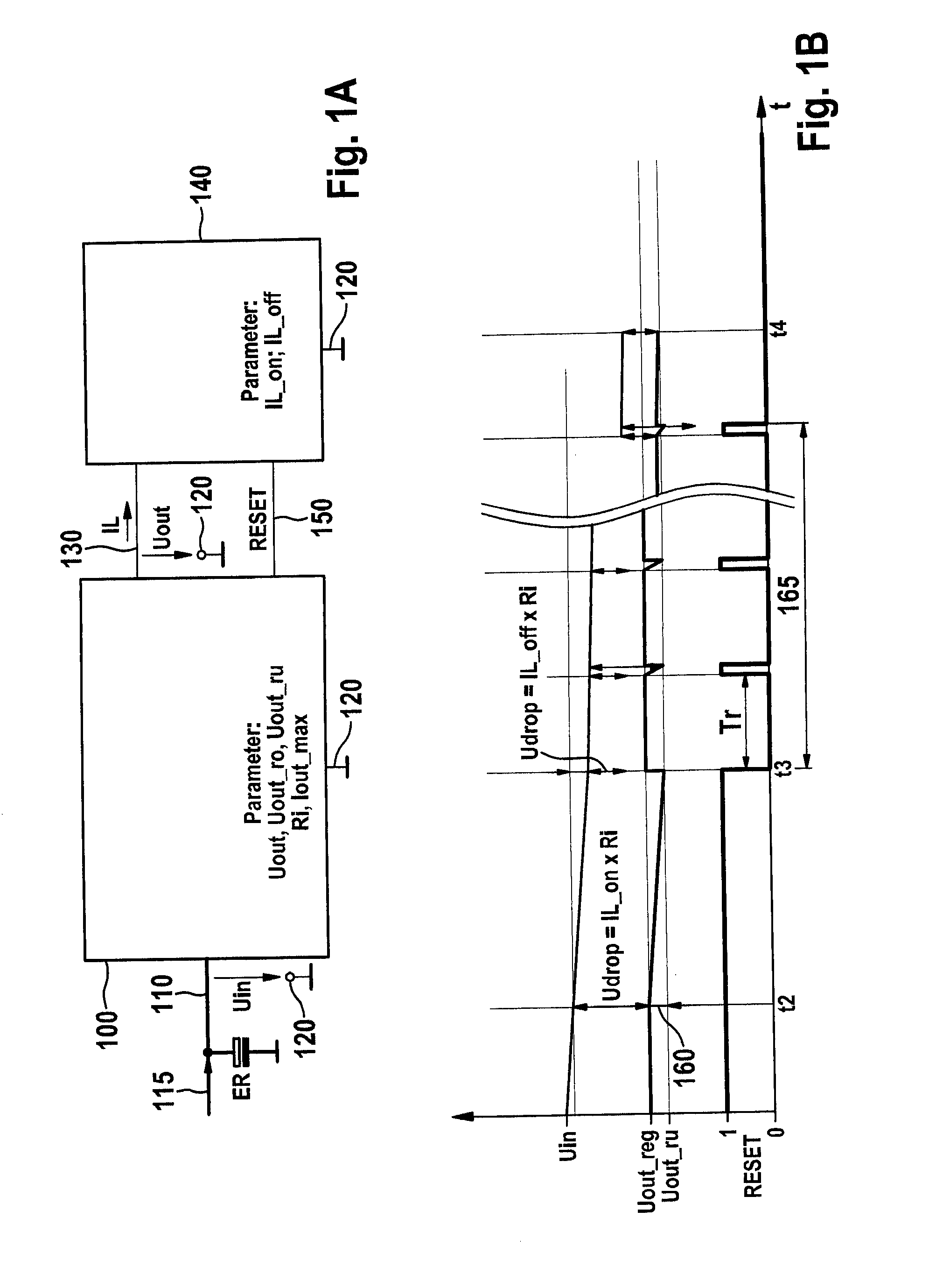
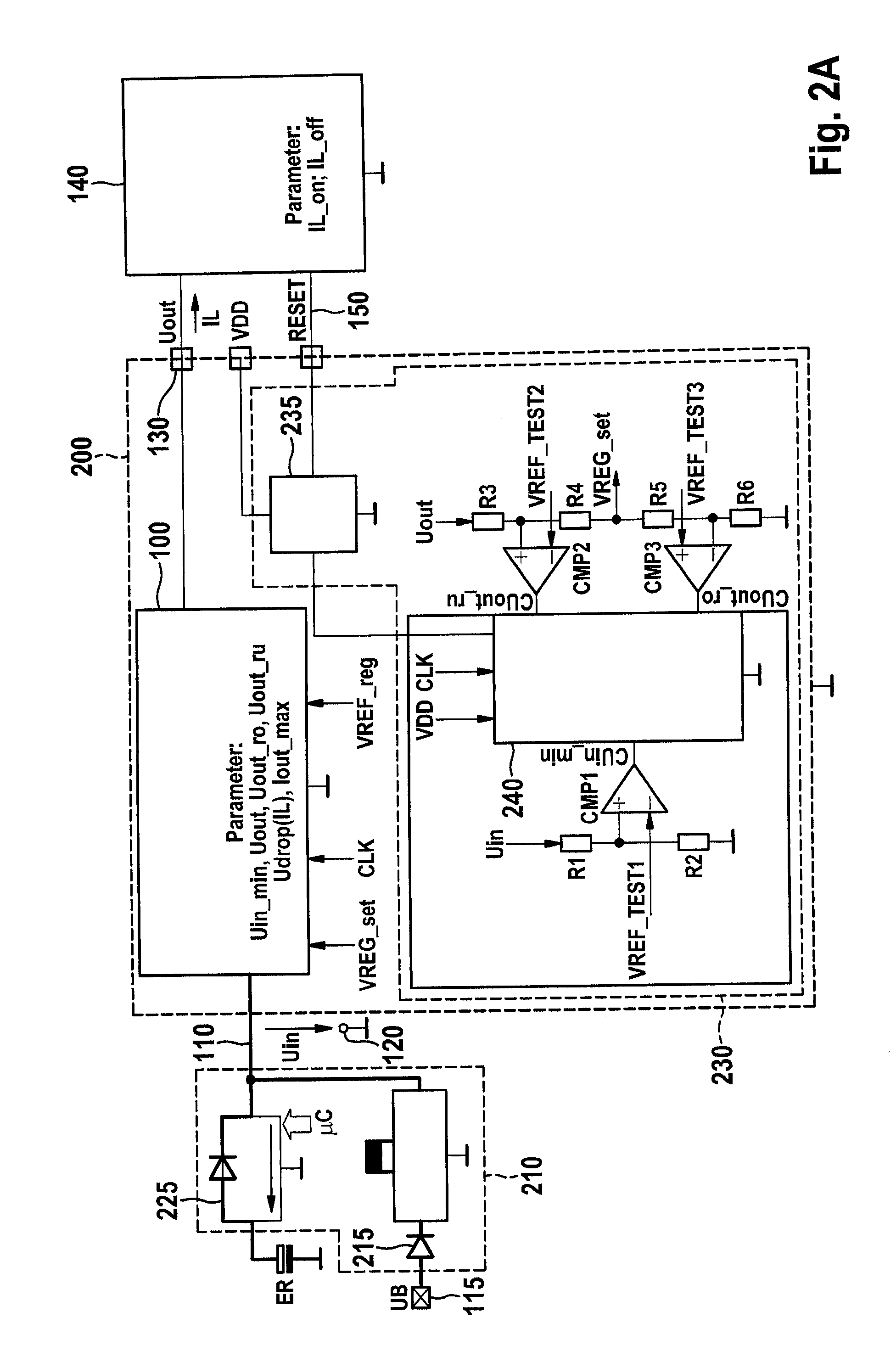
[0054]To explain the underlying problem of the approach described here, FIG. 1A shows a circuit diagram of a voltage regulator 100 which is buffered by an energy reserve ER and configured as a p-type MOSFET voltage regulator having RESET monitoring and current limiting. Voltage regulator 100 is supplied with energy from an energy reserve ER, for example a capacitor, at an input 110, energy reserve ER being charged by an energy supply network 115 and autonomously supplying the voltage regulator 100 after a decoupling of energy supply network 115. Moreover, an input voltage Uin drops between input 110 and a reference potential 120, which here is a ground potential. A regulated voltage Uout (relative to reference potential 120) is output at an output 130 of voltage regulator 100 at an output current IL, which represents an overall current which may be made available to a sum of consumers 140 by voltage regulator 100. Consumers 140 are all controllable by a RESET signal, which is output...


PUM


Abstract

An energy supply unit for supplying a consumer, includes an energy store to supply electric when the consumer is decoupled from an energy supply network. The energy supply unit includes an energy supply controller having an input coupled to the energy store, via a diode, for receiving electric energy and an output for delivering electric energy, and a monitoring unit for outputting a monitoring signal, configured to set the monitoring signal to an active state when an output voltage between the output and a reference potential is lower / greater than a predefined activation threshold value, the monitoring unit configured, when an excessively low input voltage is identified between the input and reference potential of the controller, especially paired with an excessively low output voltage, the monitoring signal is switched to the inactive state when the input voltage is above a reset threshold and the output voltage is within the monitoring band.

Description

FIELD OF THE INVENTION[0001]The present invention relates to an energy supply unit for autonomously supplying a consumer, to a method for operating an energy supply unit for autonomously supplying a consumer, and to a corresponding computer program product.BACKGROUND INFORMATION[0002]Voltage regulators are monitored with respect to their output voltage in safety-relevant systems. If the input voltage of such a voltage regulator slowly decreases, as is possible in buffered energy reserve-based systems (airbag, etc.), the output voltage is reduced when a drop below a minimal control input voltage occurs. When the output voltage reaches a lower monitoring limit, a RESET signal (for the identification of an undervoltage at the regulator output) is triggered, which may be used as a monitoring signal to control consumers connected to the regulator. This RESET (i.e., the monitoring signal RESET) resets all digital states to the starting state and stops clocked program processing steps and ...

Claims


Application Information

Patent Timeline
IPC IPC(8): B60R21/017G01R19/165H02J9/06
CPCB60R21/0173Y10T307/615G01R19/16542H02J9/061G01R19/16538
Inventor LIST, CARSTENSCHUMACHER, HARTMUTSIEVERS, FALKO
Owner ROBERT BOSCH GMBH
Learn More