A piping body having an RFID tag

A technology for RFID tags and pipes, which is applied in the direction of recording carriers, drill pipes, pipes, etc. used by machines, and can solve problems such as small range, damage, and wear of ID tags

Inactive Publication Date: 2017-08-29
TUBOSCOPE NORGE AS
View PDF12 Cites 3 Cited by
  • Summary
  • Abstract
  • Description
  • Claims
  • Application Information

AI Technical Summary

Problems solved by technology

It has also been demonstrated that relatively large pressure changes in the well adversely affect the attachment of the ID tag in the tube
[0006] The devices according to the prior art present disadvantages related to usability and / or reliability, among other things, since the range of the signal from the ID tag is relatively small, the ID tag is subject to wear and may be damaged during the assembly of the tube

Method used


Image

  • A piping body having an RFID tag
  • A piping body having an RFID tag
  • A piping body having an RFID tag

Examples


Embodiment Construction

[0026] The embodiments discussed above and described below illustrate rather than limit the invention, and those skilled in the art will be able to design many alternative embodiments without departing from the scope of the appended claims. In the claims, any reference signs placed between parentheses shall not be construed as limiting the claim. Use of the verb "comprise" and its conjugations does not exclude the presence of elements or steps other than those stated in a claim. The article "a" or "an" preceding an element does not exclude the presence of a plurality of such elements. The invention can be implemented by means of hardware comprising several distinct elements. In a device claim enumerating several means, several of these means may be embodied by one and the same item of hardware. The mere fact that certain measures are recited in mutually different dependent claims does not indicate that a combination of these measures cannot be used to advantage.

[0027] f...


PUM


Abstract

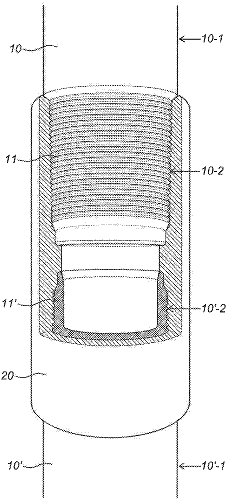
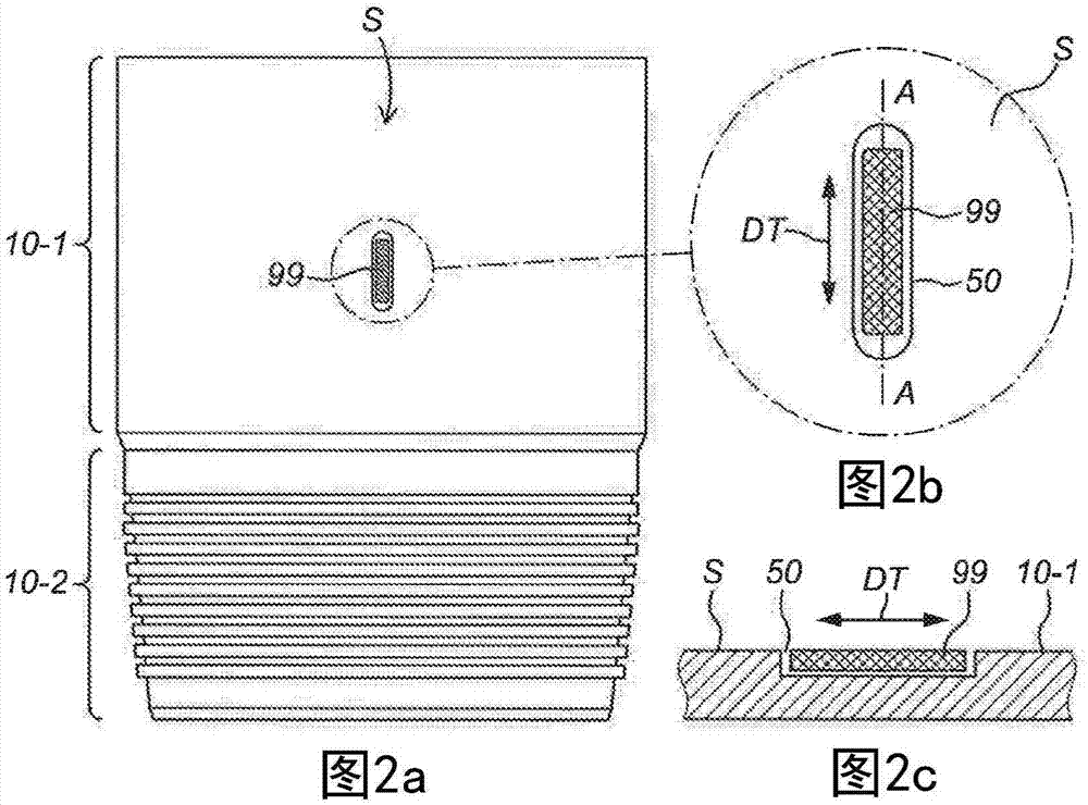
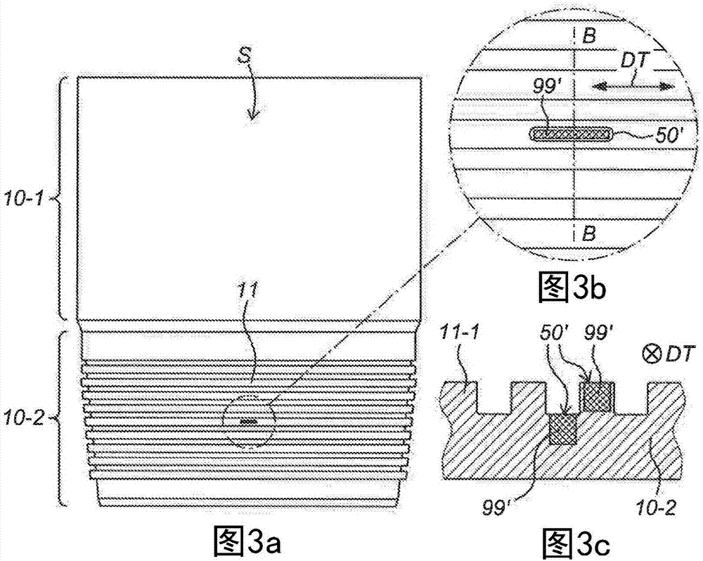
The invention relates to a piping (10) for use in an oil or gas environment, wherein the piping (10) is provided with an RFID tag (99,99',99'') for identifying said piping (10), wherein said piping (10) comprises a first end section (10-2) for being coupled to a second piping (10') and a second end section (10-2) for being coupled to a third piping, wherein said piping (10) further comprises a mid-section (10-1) in between said end sections (10-2). The RFID tag (99,99',99'') is provided in an elongate recess (50,50',50'') that is formed in the piping (10) and wherein said recess (50,50',50'') extends in a tangential direction (DT) parallel to a surface (S) of the mid-section (10- 1) of the piping (10).

Description

technical field [0001] The present invention relates to a pipeline structure or tubular structure for use in an oil or gas (oil or gas) environment, wherein said pipeline is provided with radio frequency identification (RFID) tags for identification purposes. Background technique [0002] During drilling operations, eg as commonly associated with oil extraction, a considerable number of pipes are used which are screwed together to form a pipe string. The string may also include other equipment such as controls and valve sections. Such wells are usually lined with casing to protect the borehole. [0003] In order to record the number of parts of the equipment and the physical condition of the parts, it has proven useful to monitor the service time and stress of the individual pipes and associated equipment, and to record the quantity and position of the individual pipes in the pipe string. [0004] It is known that electronic ID tags (electronic ID tags) are placed on the p...

Claims


Application Information

Patent Timeline
IPC IPC(8): E21B17/08E21B17/00E21B17/02G06K19/077F16L9/00G01S13/75
CPCG06K19/077F16L2201/60G06K19/07758E21B17/006E21B17/00G06K19/06E21B17/042F16L15/001G06K19/0723
Inventor K·E·德雷达尔H·哈尔沃森
Owner TUBOSCOPE NORGE AS
Why Eureka
Try Eureka