Device for exhaust waste heat recovery

A particle filter and regeneration process technology, applied in the electronic control of exhaust treatment devices, diagnostic devices of exhaust treatment devices, exhaust treatment, etc., can solve problems such as internal combustion engine damage, fuel consumption impact, impact, etc. Achieve the effect of reducing impact and prolonging the replacement interval

Active Publication Date: 2017-08-29
FPT IND
View PDF4 Cites 4 Cited by
  • Summary
  • Abstract
  • Description
  • Claims
  • Application Information

AI Technical Summary

Problems solved by technology

This mixing has an effect on the internal combustion engine, which can be damaged, and also has an effect on fuel consumption

Method used


Image

  • Device for exhaust waste heat recovery
  • Device for exhaust waste heat recovery
  • Device for exhaust waste heat recovery

Examples


Embodiment Construction

[0029] The method of the present invention will now be described, which is automatically activated when the process for regenerating the vehicle's DPF is initiated. After its activation, the method runs continuously and stops when the regeneration process is interrupted by the method.

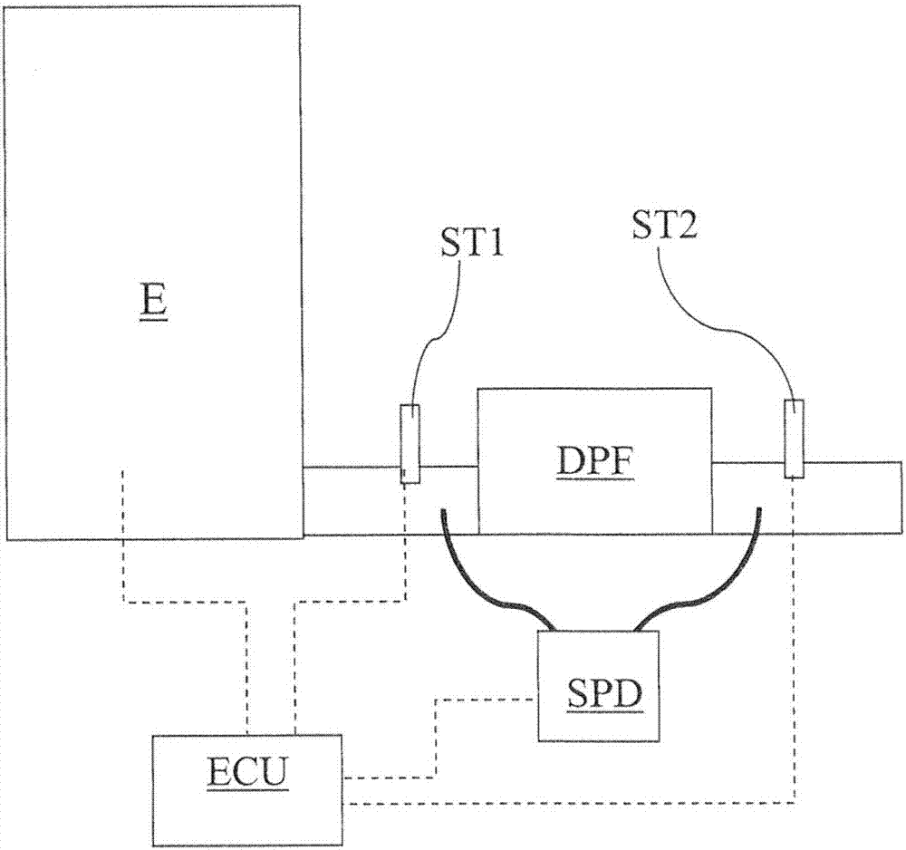
[0030] According to the method of the present invention, the temperature is measured at the outlet of the DPF and the measured temperature is compared with a calculated theoretical value to obtain a temperature difference. When the temperature difference is below a first predetermined threshold, the regeneration process is interrupted.

[0031] In order to obtain the stability of the regeneration process, it is preferable to carry out the temperature monitoring after a predetermined time interval from the start of the regeneration process.

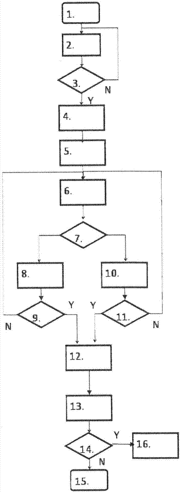
[0032] figure 1 A preferred embodiment of the first variant of the invention is shown by means of a flow chart comprising the following sequential steps....


PUM


Abstract

In one embodiment, an exhaust waste heat recovery system includes a first exhaust waste heat recovery assembly including a central exhaust channel configured to allow passage of exhaust along an exhaust axis, and a first plurality of thermoelectric (TE) legs, each of the first plurality of TE legs including a hot end in thermal communication with the exhaust channel, and a cold end opposite to the hot end, and an electrical coupler in electrical communication with each of the first plurality of TE legs, the electrical coupler configured to receive electricity from the first plurality of TE legs.

Description

technical field [0001] The present invention relates to the field of internal combustion engines, and in particular to the management of these components to reduce pollutants. More specifically, the present invention relates to methods and systems for managing the regeneration of particulate filters. Background technique [0002] DPF filters have long been used to confine particulates produced by the combustion of internal combustion engines, particularly diesel engines. [0003] These filters are called closed filters in terms of the shape of the channels formed therein. [0004] These channels are made of a porous ceramic material in order to retain the particles contained in the gas passing through the channels. [0005] Filter clogging is detected by measuring the pressure upstream of the filter (back pressure) or by measuring the differential pressure upstream and downstream of the filter. [0006] Depending on the usage of the vehicle, the particulate filter may be ...

Claims


Application Information

Patent Timeline
Patent Type & Authority Applications(China)
IPC IPC(8): F01N9/00F01N3/023
CPCF01N3/023F01N9/002F01N2900/1404F01N2900/1406Y02T10/40F01N3/021F01N11/00
Inventor 乔瓦尼·切尔切洛安杰拉·维蒂耶洛
Owner FPT IND
Why Eureka
Try Eureka