Dynamic Measurement of Synthesizer Noise Spurs or Phase Noise

A technology of frequency synthesizer and phase noise, applied in noise figure or signal-to-noise ratio measurement, automatic control of power, measurement device, etc., can solve problems such as unreliable radar measurement

Active Publication Date: 2020-09-22
TEXAS INSTR INC
View PDF5 Cites 0 Cited by
  • Summary
  • Abstract
  • Description
  • Claims
  • Application Information

AI Technical Summary

Problems solved by technology

Therefore, high phase noise or spurs can render radar measurements unreliable

Method used


Image

  • Dynamic Measurement of Synthesizer Noise Spurs or Phase Noise
  • Dynamic Measurement of Synthesizer Noise Spurs or Phase Noise
  • Dynamic Measurement of Synthesizer Noise Spurs or Phase Noise

Examples


no. 1 example

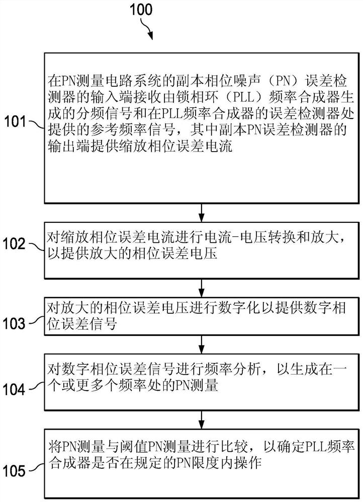
[0038] This process is illustrated for the first embodiment using the equations or process steps described below:

[0039] a. Let x[n] be the digital samples output by the ADC of the PN measurement circuitry. Take N such consecutive samples. Thus, x[n], where n=0 to N-1, can be used as a block sequence of numbers in the processor's memory.

[0040] b. Perform FFT on x[n] to obtain FFT result X[k], where k=0 to N-1.

[0041] c. Find the signal Y[k]=X[k]*X[k], where the operation ".*" means element-wise multiplication. For example, Y[0]=X[0]*X[0], where "*" means multiplication. In other embodiments, Y[k]=|X[k]| may be found to have equivalent PN measurement performance. Here, |X[k}]| denotes the absolute value of the sequence X[k], and the meaning of "absolute value" is well known to mathematicians and engineers.

[0042] d. Optionally, repeat steps a, b, c more (eg L) times (iteration i=1 to L). The digital samples are different for each acquisition because new acquisiti...


PUM


Abstract

In the described example of the method (100) of measuring phase noise (PN), the PLL frequency synthesizer comprises a first phase frequency detector (PFD) receiving (101) a reference frequency signal, the first phase frequency detector ( PFD) is coupled to a first charge pump (CP) coupled to a VCO having an output fed back to the first PFD through a feedback divider that provides a divided signal to the first PFD. The first PFD outputs an error signal. The PN measurement circuitry includes a replica CP coupled to the output of the second PFD or the first PFD. The error signal is received at the replica CP, or the frequency-divided signal and the reference frequency signal are received at the second PFD. The replica CP outputs a scaled phase error current, which is current-voltage converted and amplified (102) to provide an amplified phase error voltage, and digitized (103) to provide a digital phase error signal. Frequency analysis (104) is performed on the digital phase error signal to generate a PN measurement.

Description

technical field [0001] This application is concerned with the dynamic measurement of noise spurs or phase noise generated by frequency synthesizers. Background technique [0002] A frequency synthesizer includes an electronic system that generates (one or more) higher frequency signals at its output from lower frequency signals received from a single fixed time base or master oscillator. A common way to implement a frequency synthesizer is to use a phase-locked loop (PLL). [0003] A PLL is a feedback control system that includes an error detector (including a phase-frequency detector coupled to a charge pump) that compares the phases of two input signals (a reference frequency signal and a divided, higher frequency output signal) compared to produce an error signal proportional to the difference between their phases. This error signal is then low pass filtered and used to drive a voltage controlled oscillator (VCO), which produces a higher output frequency. This output f...

Claims


Application Information

Patent Timeline
Patent Type & Authority Patents(China)
IPC IPC(8): G01R29/06G01S13/931
CPCG01S7/03G01S7/4008G01S7/4017G01S13/343G01S13/345G01S13/931G01R29/26H03L7/06
Inventor K·苏布拉吉S·斯玛拉R·加内桑
Owner TEXAS INSTR INC
Why Eureka
Try Eureka