Safe Electric Braking Devices for Synchronous Motors

A synchronous motor and mechanical brake technology, applied in the field of rail vehicles, can solve the problems of complicated converter adjustment, difficult and error-free control, etc., and achieve the effects of increased complexity, low complexity, and simple safety.

Active Publication Date: 2019-05-21
SIEMENS MOBILITY GMBH
View PDF8 Cites 0 Cited by
  • Summary
  • Abstract
  • Description
  • Claims
  • Application Information

AI Technical Summary

Problems solved by technology

However, the regulation of the converter based on its multiple input parameters and internal calculation steps is very complex
For this reason, it is difficult to achieve an error-free control for all possible vehicle and operating states

Method used


Image

  • Safe Electric Braking Devices for Synchronous Motors
  • Safe Electric Braking Devices for Synchronous Motors
  • Safe Electric Braking Devices for Synchronous Motors

Examples


Embodiment Construction

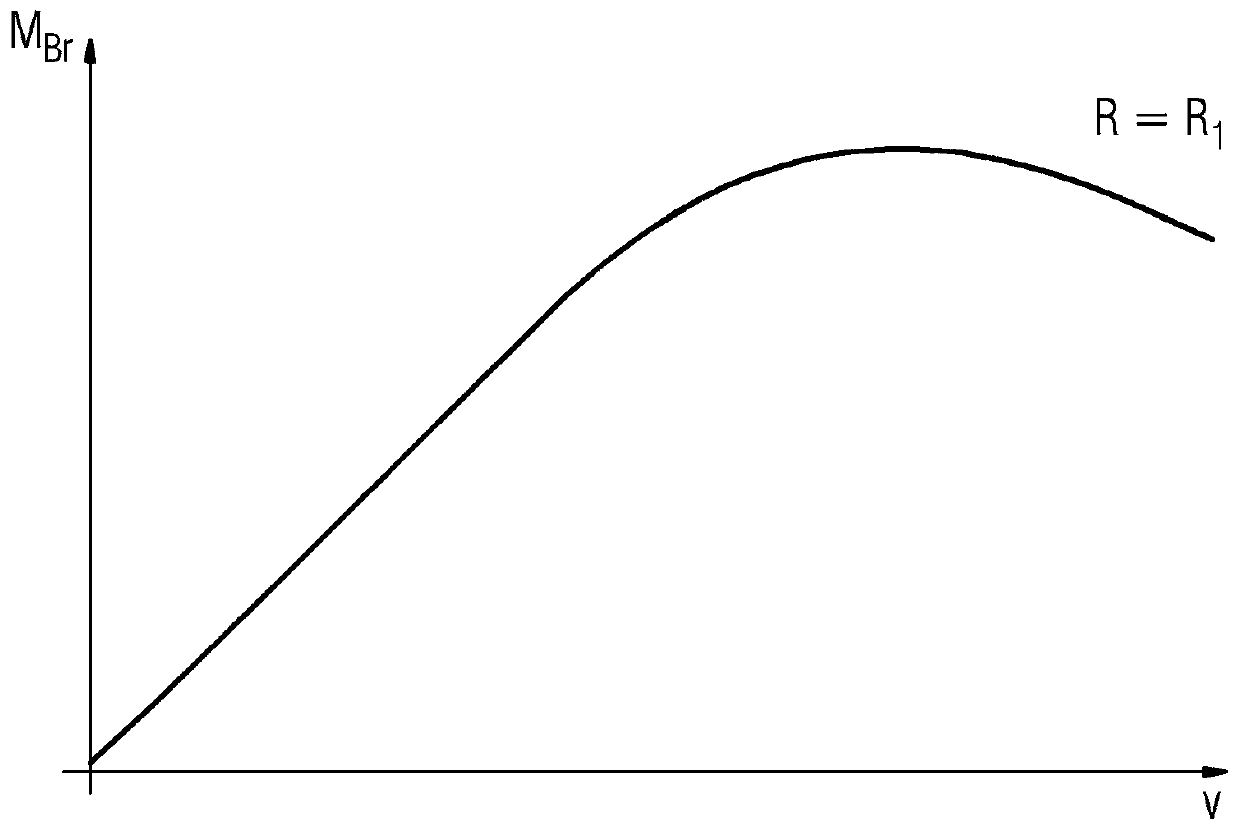
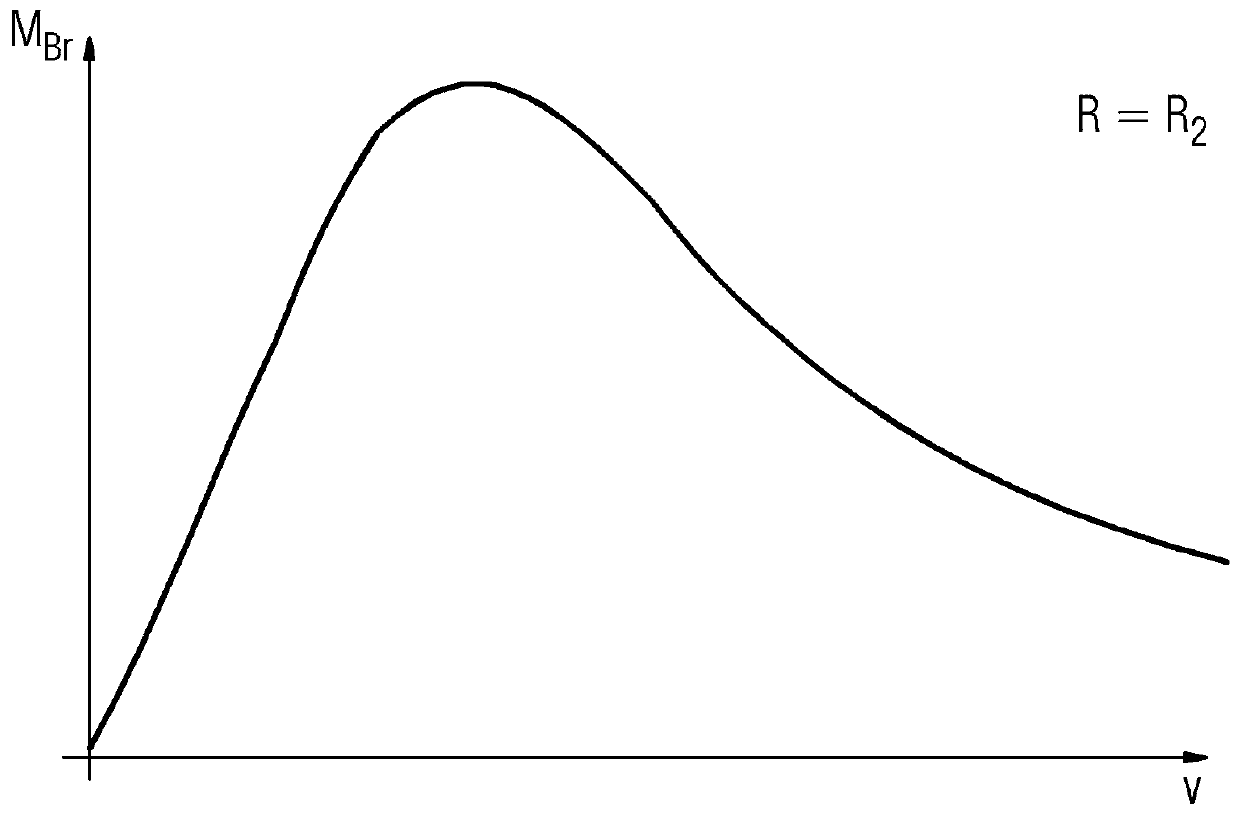
[0031] figure 1 shows the respective electrical connections at the phase connectors 20 with the value R 1 The braking torque M in the case of resistor 4 Br Curves against rotational speed. For values ​​with value R 2 The second resistor 4, where R 2 1 , whose curve is as figure 2 shown. Obviously, for a smaller resistance 4 a braking torque M occurs at a smaller speed Br the maximum value. At zero rotational speed, no braking torque M can be achieved at the synchronous motor 2 independently of the resistance value Br . In order to be able to apply a braking torque to the drive system in the stationary state, an additional brake, for example a mechanical brake, must be provided in the drive system 1 .

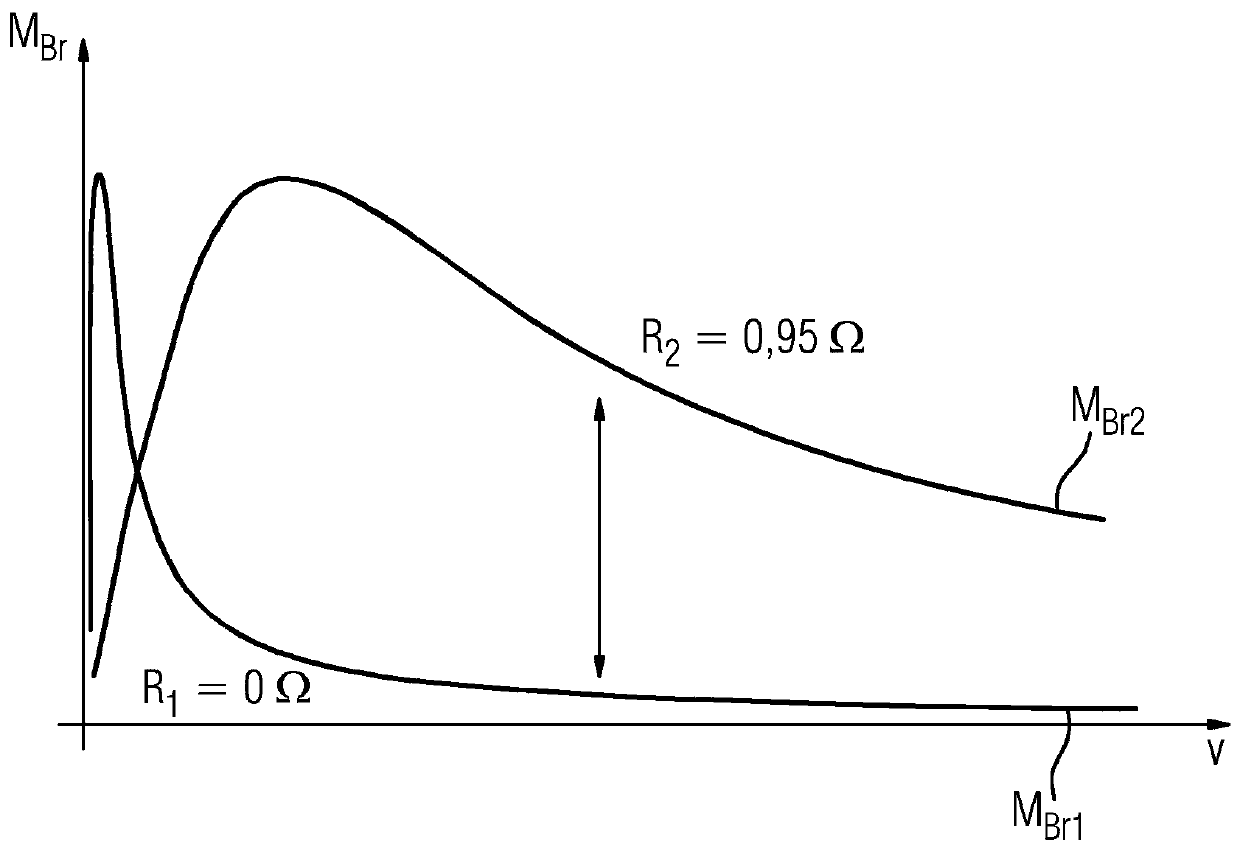
[0032] image 3 shows the first braking torque M Br1 The curve and the second braking torque M Br2 , where the first braking torque occurs when the phase connections 20 of the synchronous machine 2 are short-circuited, and in the case of the second braking torque, t...


PUM


Abstract

The invention relates to a method for safely controlling the braking torque of a drive system (1). In order to be able to control the braking torque safely, it is proposed that the drive system (1) has a synchronous motor (2) and a switching device (3), wherein the synchronous motor (2) has a phase connection (20), wherein the switching device (3) In a state, the phase joints (20) are connected to each other in order to generate a first braking torque (M Br1 ), and are connected to each other with the phase joint (20) in the second state so as to generate a second braking torque (M at the synchronous motor (2) Br2 ), wherein the switching device (3) switches between these states in order to give a predeterminable braking torque (M*) at the synchronous motor (2) in the mean value over time, wherein in order to generate the first braking Moment (M Br1 ) short-circuit the phase joints (20) of the synchronous motor (2), and wherein in order to generate the second braking torque (M Br2 ) connect the phase connection (20) of the synchronous motor (2) to at least one resistor (4). The invention also relates to a drive system (1) for carrying out the method and a vehicle, in particular a rail vehicle, having the drive system.

Description

technical field [0001] The invention relates to a method for safely controlling the braking torque of a drive system with a synchronous electric machine. The invention also relates to a drive system and a vehicle, in particular a rail vehicle, having such a drive system. Background technique [0002] A drive system with an inverter and a motor, also referred to as an electric machine, is able to deliver the desired torque very precisely on the shaft of the motor. This concerns not only the torque for accelerating the motor, but also the braking torque for braking the motor. [0003] This fact is precisely taken into account below on the basis of the example of a rail vehicle. Today, rail vehicles are mostly electrically driven. For this purpose, the motor can accelerate the vehicle, but can also brake it. During braking by the motor, electrical energy is fed back, which is then conducted into the power supply network or dissipated via a braking resistor. In addition to ...

Claims


Application Information

Patent Timeline
Patent Type & Authority Patents(China)
IPC IPC(8): H02P3/22B60L3/10B60L7/00B60L7/06B60L7/08B60L7/26B60L15/00B60L15/20
CPCB60L50/51B60L3/108B60L7/003B60L7/06B60L7/08B60L7/26B60L15/007B60L15/2009H02P3/22B60L2210/40B60L2220/14B60L2240/80B60L2240/12B60L2240/423B60L2200/26B60L2250/24Y02T10/64Y02T10/70Y02T10/72H02P6/24
Inventor 格拉尔德·阿姆勒汉斯·贝格纳
Owner SIEMENS MOBILITY GMBH
Why Eureka
Try Eureka