
Lapping and polishing tool and polishing machine

A polishing machine and tool technology, which is applied in the direction of manufacturing tools, grinding/polishing equipment, metal processing equipment, etc., can solve the problem of temperature rise in the center area of ​​the bottom of the polishing tool, affecting the surface shape accuracy of removal stability components, and heat cannot be brought To improve the polishing efficiency, improve the removal stability, and realize the effect of active supply

Active Publication Date: 2017-09-01
LASER FUSION RES CENT CHINA ACAD OF ENG PHYSICS
View PDF7 Cites 5 Cited by
  • Summary
  • Abstract
  • Description
  • Claims
  • Application Information

AI Technical Summary

Problems solved by technology

This will lead to less polishing particles actually participating in the polishing, thereby reducing the polishing efficiency
Moreover, since it is difficult for the polishing liquid to enter the center area of ​​the bottom of the polishing tool, the heat generated by the friction between the polishing tool and the components cannot be taken away, resulting in an increase in the temperature of the center area of ​​the bottom of the polishing tool and accelerated wear, which in turn affects the removal stability and Component Surface Accuracy

Method used


Image

  • Lapping and polishing tool and polishing machine
  • Lapping and polishing tool and polishing machine
  • Lapping and polishing tool and polishing machine

Examples


Embodiment Construction

[0027] In order to make the purpose, technical solutions and advantages of the embodiments of the present invention clearer, the technical solutions in the embodiments of the present invention will be clearly and completely described below in conjunction with the drawings in the embodiments of the present invention. Obviously, the described embodiments It is a part of embodiments of the present invention, but not all embodiments. The components of the embodiments of the invention generally described and illustrated in the figures herein may be arranged and designed in a variety of different configurations.

[0028] Accordingly, the following detailed description of the embodiments of the invention provided in the accompanying drawings is not intended to limit the scope of the claimed invention, but merely represents selected embodiments of the invention. Based on the embodiments of the present invention, all other embodiments obtained by persons of ordinary skill in the art wi...


PUM


Abstract

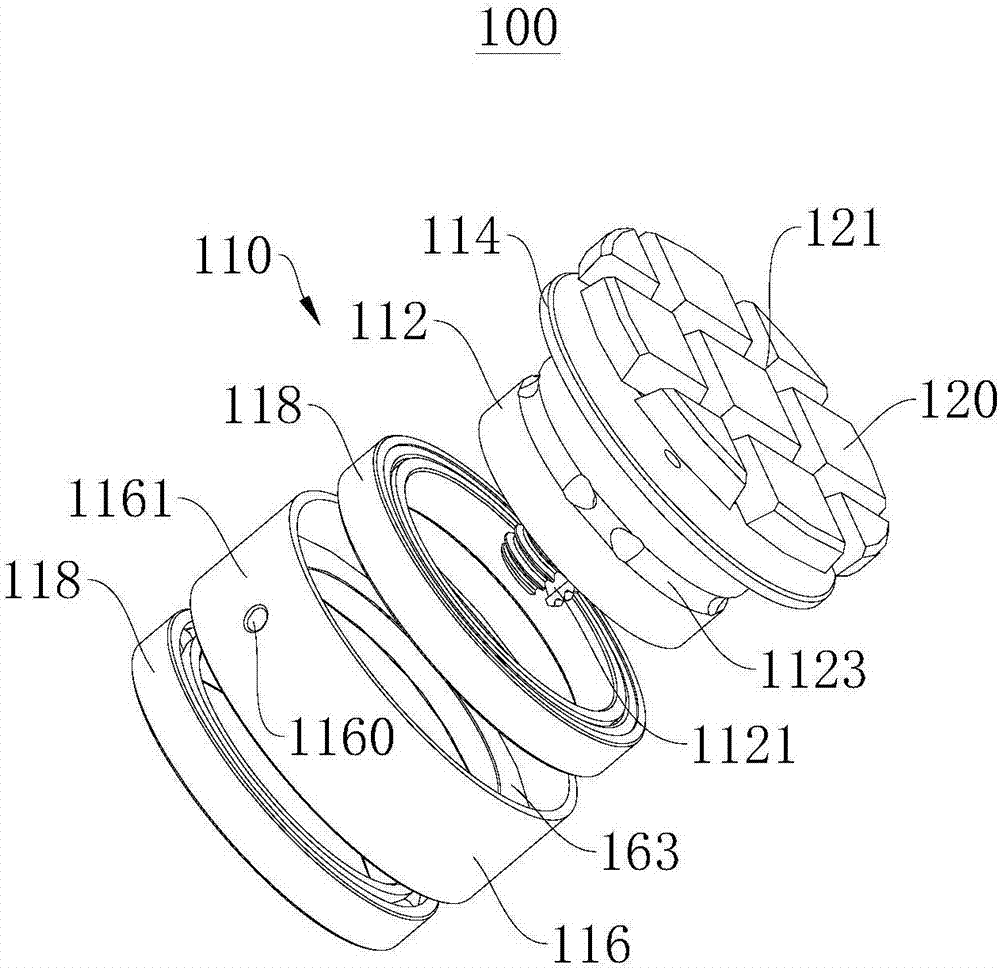
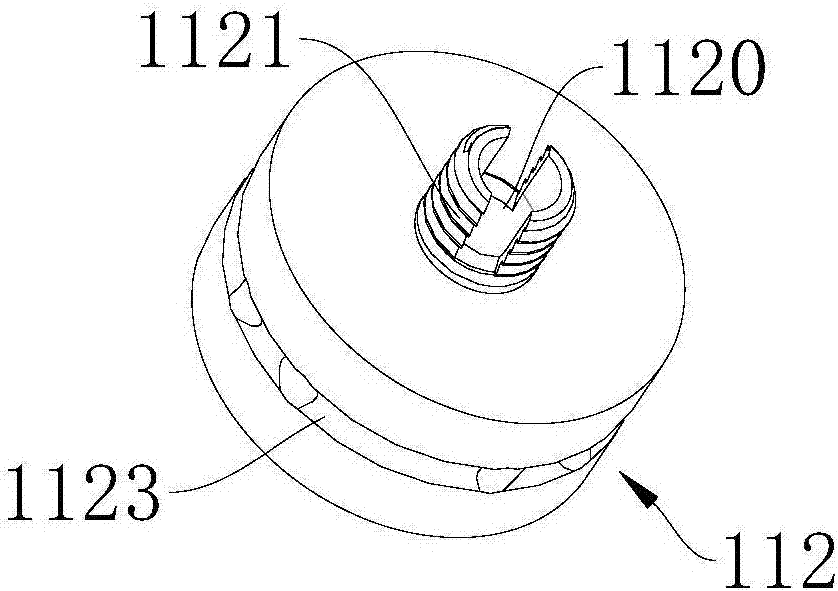
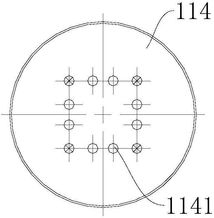
The invention provides a lapping and polishing tool and a polishing machine, and relates to the technical field of computer control optical surface formation. The lapping and polishing tool is used for being mounted on the polishing machine; the polishing machine comprises a polishing machine body; the lapping and polishing tool comprises a polishing component and a polishing mold layer; the polishing component comprises a flow guide part; the polishing mold layer is connected with one side of the flow guide part; the other side of the flow guide part is used for being connected with the polishing machine body; the flow guide part is provided with a fluid channel; the polishing mold layer is provided with a liquid outlet channel; one end of the fluid channel communicates with the liquid outlet channel; and the other end of the fluid channel penetrates through the flow guide part. The lapping and polishing tool has the benefits as follows: the distribution uniformity of a polishing solution is effectively controlled, the polishing solution is enabled to permeate into the bottom of the polishing tool, the polishing efficiency is improved, lot of heat in the central area at the bottom of the lapping and polishing tool is carried away, the element surface is stably polished, and the element surface figure accuracy is high; as the polishing machine provided by the invention adopts the lapping and polishing tool, the polishing efficiency is further improved, the element surface is stably polished, and the element surface figure accuracy is high.

Description

technical field [0001] The invention relates to the technical field of computer-controlled optical surface shaping, in particular to a polishing tool and a polishing machine. Background technique [0002] Computer Controlled Optical Surfacing (CCOS) is an optical processing technology developed in the 1970s. Compared with traditional processing technology, it greatly reduces the dependence on operator experience. The core idea of ​​this technology is to use a computer to control a small-sized processing tool (or polishing tool) that is much smaller than the workpiece to be processed, to polish the surface of the workpiece with a certain trajectory, speed and pressure, and to control the relative movement between the tool and the workpiece. The speed, pressure and the residence time of the tool on a certain area of ​​the surface are used to control the amount of material removal, so that the surface error of the part can be quickly converged. In the CCOS process, the polishi...

Claims


Application Information

Patent Timeline
Patent Type & Authority Applications(China)
IPC IPC(8): B24B13/00B24B13/01B24B57/02
CPCB24B13/00B24B13/01B24B57/02Y02P70/10
Inventor 文中江钟波陈贤华王健许乔
Owner LASER FUSION RES CENT CHINA ACAD OF ENG PHYSICS
Learn More