
New energy electric quadrotor UAV

A quad-rotor UAV, new energy technology, applied in the directions of rotorcraft, motors, electric components, etc., can solve the problems of poor endurance of quad-rotor UAV, restriction of rapid development of UAV, large size of the device, etc. Lightweight, firm locking, and compact effect

Active Publication Date: 2019-04-02
泰山人才发展集团有限公司
View PDF5 Cites 0 Cited by
  • Summary
  • Abstract
  • Description
  • Claims
  • Application Information

AI Technical Summary

Problems solved by technology

[0002] At present, many technologies in the field of drones in my country have reached the world's advanced level. Because quadrotor drones have good stability, strong operability, and wide range of uses, various quadrotor drones are developing extremely rapidly, but The rapid development of UAVs in the military field and civilian direction is restricted to some extent due to reasons such as poor endurance of the existing quadrotor UAVs.
In the existing technical solutions, the technology of charging the UAV with a fixed charging station is generally used, or the battery of the rotor UAV is improved, and the motor with a higher efficiency is used to improve the range of the UAV. Rotary-wing unmanned aerial vehicle autonomous endurance charging pile and its method", the invention application with the patent number "2016110115937", discloses a technical solution for unmanned aerial vehicles to independently search for charging stations for charging when the power is insufficient. This is a kind of An effective charging pile solution, when the charging pile charges the UAV, it controls the closing of the four triangular covers and completely wraps the rotor UAV in the charging pile. Its shortcoming lies in: the charging pile locks the UAV The device is large in size and complex in structure. In addition, this rotor UAV has no other improvement scheme to improve the range of the UAV.

Method used


Image

  • New energy electric quadrotor UAV
  • New energy electric quadrotor UAV
  • New energy electric quadrotor UAV

Examples


Embodiment Construction

[0014] The present invention will be further described below in conjunction with the accompanying drawings and embodiments.

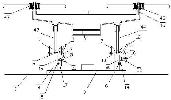
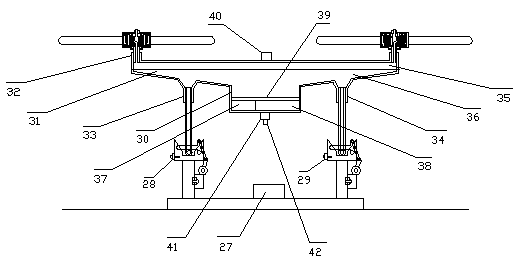
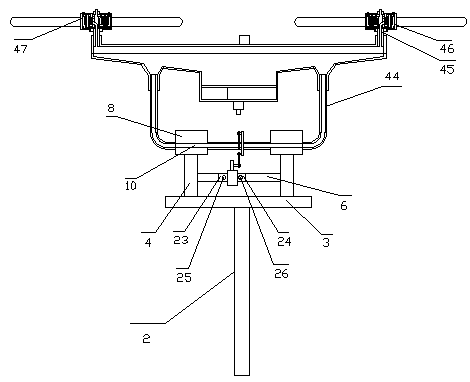
[0015] exist figure 1 , figure 2 , image 3 , Figure 4 Among them, the new energy and new electric quadrotor drones are set up with a round-trip aviation route, and several smart charging piles are set on the aviation route. Several smart charging piles are set on the roof 1 above the city; they are set on the utility pole 2 above the countryside At the upper end, the smart charging pile is provided with a rectangular platform 3, the rectangular platform is installed on the roof or the upper end of the utility pole, the four corners of the rectangular platform are provided with insulating columns 4, and the left connecting plate 5 is installed between the front and rear insulating columns on the left, and the right The right connecting plate 6 is installed between the front and rear insulating columns, the live wire front and rear power supply tank...


PUM


Abstract

A new energy and new electric quadrotor UAV is composed of a smart charging pile and a new electric quadrotor UAV. The smart charging pile is equipped with a rectangular platform and an intelligent control box. The upper ends of the four insulating columns of the rectangular platform are equipped with power supply tanks. The electric quadrotor UAV is equipped with a cross-shaped fuselage, and 4 outer rotor coreless motors are installed on the 4 hollow shafts at the four corners of the cross-shaped fuselage. The position of the intelligent charging pile falls within the error range of the GPS, and the visual sensing of the camera tracks the rectangular platform and the intelligent control box. The left and right T-shaped locks are controlled by computer and have the functions of opening, locking and closing the drone. The locking device is small in size, simple in structure, reliable and low in cost; the four outer rotor coreless motors have high efficiency , Small in size and light in weight, it has the outstanding effect of improving the flight range of drones.

Description

technical field [0001] The invention relates to a quadrotor UAV, specifically a new energy new electric quadrotor UAV. Background technique [0002] At present, many technologies in the field of drones in my country have reached the world's advanced level. Because quadrotor drones have good stability, strong operability, and wide range of uses, various quadrotor drones are developing extremely rapidly, but Due to reasons such as poor endurance of the existing quadrotor UAVs, the rapid development of UAVs in the military and civilian fields is restricted to a certain extent. In the existing technical solutions, the technology of charging the UAV with a fixed charging station is generally used, or the battery of the rotor UAV is improved, and the motor with a higher efficiency is used to improve the range of the UAV. Rotary-wing unmanned aerial vehicle autonomous endurance charging pile and its method", the invention application with the patent number "2016110115937", disclose...

Claims


Application Information

Patent Timeline
Patent Type & Authority Patents(China)
IPC IPC(8): B60L53/31B64C27/08B64D27/24B64D47/08G05D1/12H02K1/27H02K1/12H02K3/47H02K3/28H02K11/215
CPCH02K1/12H02K1/2786H02K3/28H02K3/47H02K11/215G05D1/12B64C27/08B64D27/24B64D47/08B60L53/60B60L2200/10B64U2201/104B64U10/10B64U50/19Y02T90/16Y02T10/64Y02T10/70Y02T50/60Y02T90/12Y02T10/7072
Inventor 朱幕松
Owner 泰山人才发展集团有限公司
Learn More