Eureka AIR delivers breakthrough ideas for toughest innovation challenges, trusted by R&D personnel around the world.

Vacuum pipeline ultra-high speed train

A vacuum pipeline and ultra-high-speed technology, applied to motor vehicles, electric vehicles, railway car bodies, etc., can solve the problems of airflow congestion, high energy consumption for passenger comfort, etc., to reduce resistance, eliminate shock wave resistance, and reduce aerodynamic resistance and the effect of frictional resistance

Pending Publication Date: 2017-09-01
HIWING TECH ACAD OF CASIC
View PDF4 Cites 8 Cited by
  • Summary
  • Abstract
  • Description
  • Claims
  • Application Information

AI Technical Summary

Problems solved by technology

[0004] In view of this, the present invention provides a vacuum tube ultra-high-speed train, which can solve the problems of airflow congestion, passenger comfort and high energy consumption in the vacuum tube by rationally designing the size parameters of the car body and the vacuum tube

Method used


Image

  • Vacuum pipeline ultra-high speed train
  • Vacuum pipeline ultra-high speed train

Examples


Embodiment Construction

[0015] The present invention will be described in detail below with reference to the accompanying drawings and examples.

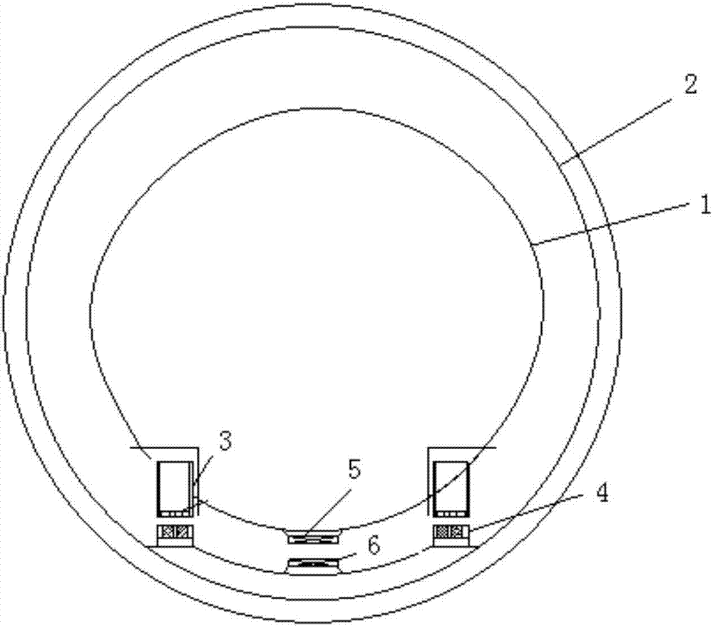
[0016] as attached figure 1 As shown, the present invention provides a vacuum tube ultra-high-speed train, which comprises a vacuum tube 2, a car body 1, a suspension device 3 on the car, a permanent magnet track 4, a vehicle-mounted propulsion device 5, a propulsion coil 6, and a vehicle-mounted battery and control system;

[0017] The interior space of the car body 1 is divided into a control room, a passenger room, a luggage room and an on-board battery room sequentially along the length direction.

[0018] Two rows of superconducting blocks and a suspension device 3 on the vehicle composed of two rows of superconducting blocks and a liquid nitrogen Dewar are installed side by side on the outer sides of the bottom of the vehicle body 1. The suspension device on the vehicle and the permanent magnetic track 4 laid on the inner bottom of the vacuum pipeli...


PUM

PropertyMeasurementUnit
Widthaaaaaaaaaa
Heightaaaaaaaaaa
Lengthaaaaaaaaaa

Abstract

The invention discloses a vacuum pipeline ultra-high speed train comprising a vacuum pipeline, a train body, on-train suspension devices, a train-mounted propelling device, electrical equipment and a controlling system. The on-train suspension devices are parallelly mounted on the two edges, close to the outer side, of the bottom of the train body side by side to achieve train body suspension along with permanent magnetic railways laid on the inner bottom face of the vacuum pipeline. A superconducting magnet and a Dewar container are arranged in the middle of the bottom of the train body to propel the train along with a propelling coil laid on the inner bottom face of the vacuum pipeline. The diameter ratio of the train body to the vacuum pipe is 0.5-0.7, and the cross section area ratio of the train body to the vacuum pipe is 0.3-0.5. The electrical equipment supplies electricity to electric equipment inside the train body, the on-train suspension devices and train-mounted propelling device, and the control system controls the operation speed of the train body by controlling the magnitude of currents in the on-train suspension devices and train-mounted propelling device. By reasonably designing size parameters of the train body and the vacuum pipeline, the problems of air flow jamming, low passenger comfort and high energy consumption in the vacuum pipeline can be solved.

Description

technical field [0001] The invention relates to an ultra-high-speed train system, in particular to a vacuum magnetic levitation train with a maximum running speed close to the speed of sound to supersonic speed, and belongs to the technical field of magnetic levitation trains. Background technique [0002] With the continuous improvement of train speed, the aerodynamic resistance of the train is also increasing rapidly. The friction between the wheel-rail train and the track brings resistance and friction problems. In order to solve these two problems and greatly increase the train speed, a vacuum tube magnetic levitation has appeared. Transportation system concept. However, the following problems will occur when the train runs at super high speed (close to the speed of sound or supersonic speed) in the vacuum pipeline: airflow congestion occurs in the vacuum pipeline, the excessive cross-sectional area of ​​the train will increase the diameter of the pipeline sharply, and t...

Claims


Application Information

Patent Timeline
IPC IPC(8): B60L13/10B61B13/08B61D17/02
CPCB61B13/08B61D17/02B60L13/10B60L2200/26Y02T30/00
Inventor 毛凯黄承静赵明李少伟林晔刘国鉴
Owner HIWING TECH ACAD OF CASIC
Why Eureka
Eureka Blog
Learn More