Bidirectional automatic door closing device realizing fast mounting
A technology for automatic door closing and equipment, applied in door/window accessories, leaf shutters, buildings, etc., can solve problems such as inconvenient installation, and achieve the effect of convenient replacement, simple structure, and simplified installation difficulty.
- Summary
- Abstract
- Description
- Claims
- Application Information
AI Technical Summary
Problems solved by technology
Method used
Image
Examples
Embodiment 1
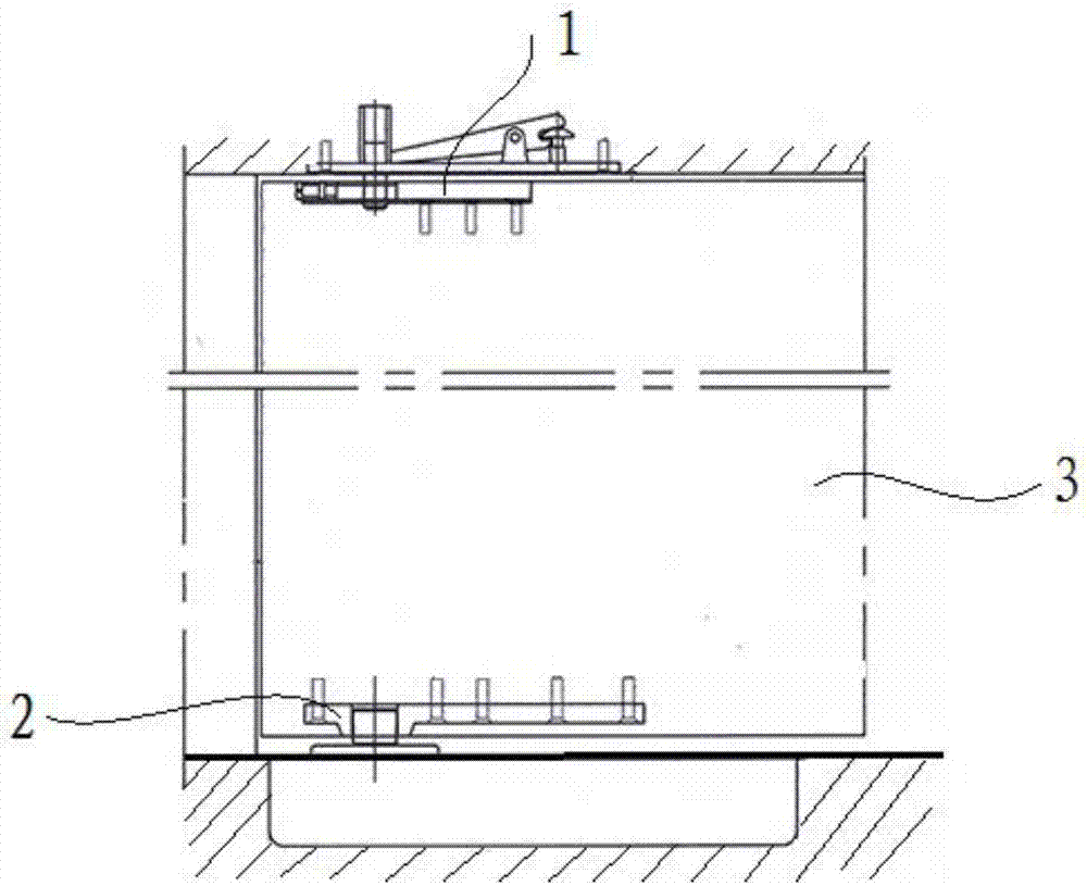
[0072] This embodiment provides a two-way automatic door closing device that realizes quick installation, figure 1 A schematic diagram of the installation of the device is given, see figure 1 , the device includes: an upper shaft assembly 1 connected to the upper part of the door 3 and a lower shaft assembly 2 connected to the lower part of the door 3 .
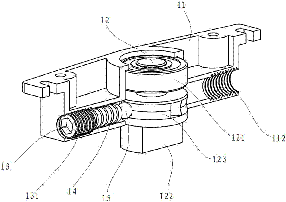
[0073] figure 2 A cross-sectional view of the upper shaft assembly of the device of this embodiment is given. See figure 2 , The upper shaft assembly 1 includes: an upper housing 11 , an upper shaft 12 , a top wire 13 , a spring 14 and a steel ball 15 .
[0074] The upper casing 11 includes: an upper cavity 111 and an internal thread 112 .
[0075] The upper chamber 111 is an inverted "T"-shaped chamber composed of a cylindrical bearing chamber and two tubular spring chambers.
[0076] The internal thread 112 is located at an end of the spring cavity away from the bearing cavity.
[0077] Specifically, the internal th...
Embodiment 2
[0104] This embodiment provides another two-way automatic door closing device that realizes quick installation, figure 1 A schematic diagram of the installation of the device is given, see figure 1 , the device includes: an upper shaft assembly 1 connected to the upper part of the door 3, a lower shaft assembly 2 connected to the lower part of the door 3, a door casing 31 and a bolt 4 fixed in the wall above the door 3.
[0105] Figure 6 The assembly drawing of the upper shaft assembly and the door pocket of this embodiment is given, Figure 7 A schematic structural view of the upper shaft assembly and the door pocket of this embodiment is given, Figure 8 A sectional view of the upper shaft assembly and the door pocket of this embodiment is given. See Figure 6 to Figure 8 :
[0106] The upper shaft assembly 1 includes: an upper housing 11 , an upper shaft 12 , a top wire 13 , a spring 14 and a steel ball 15 .
[0107] The upper casing 11 includes: an upper cavity 111 ...
Embodiment 3
[0142] On the basis of Embodiment 1 or Embodiment 2, this embodiment provides a two-way automatic door closing device that realizes quick installation.
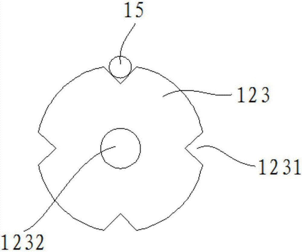
[0143] The device's grooved wheels such as Figure 9 As shown, the grooved wheel 123 includes: a groove 1231 and a through hole 1232 .
[0144] The groove 1231 is a groove parallel to the axial direction of the grooved wheel 123 located on the outer edge of the grooved wheel 123 .
[0145] The through hole 1232 is a circular hole passing through the center of the groove wheel in the axial direction, and the diameter of the through hole 1232 is equal to the diameter of the upper shaft 122 .
[0146] Specifically, the number of the grooves 1231 is four, the four grooves 1231 are distributed on the outer edge of the groove wheel 123, and the central angle of two adjacent grooves 1231 is 90°, the The through hole 1232 is located at the axis of the grooved wheel 123 , and the through hole 1232 is used for passing the upper shaft...
PUM
 Abstract
Description
Claims
Application Information
 - R&D
- Intellectual Property
- Life Sciences
- Materials
- Tech Scout
- Unparalleled Data Quality
- Higher Quality Content
- 60% Fewer Hallucinations
Browse by: Latest US Patents, China's latest patents, Technical Efficacy Thesaurus, Application Domain, Technology Topic, Popular Technical Reports.
© 2025 PatSnap. All rights reserved.Legal|Privacy policy|Modern Slavery Act Transparency Statement|Sitemap|About US| Contact US: help@patsnap.com


