
Stator blade, compressor structure and compressor

A technology for stator blades and compressors, applied in the field of compressors, can solve the problem of high air flow mixing loss, and achieve the effects of improving aerodynamic efficiency and reducing air flow mixing loss.

Inactive Publication Date: 2017-09-01
GREE ELECTRIC APPLIANCE INC OF ZHUHAI
View PDF5 Cites 12 Cited by
  • Summary
  • Abstract
  • Description
  • Claims
  • Application Information

AI Technical Summary

Problems solved by technology

[0005] In the embodiment of the present invention, a stator blade, a compressor structure and a compressor are provided to solve the problem of high air mixing loss caused by supplementary air in the prior art

Method used


Image

  • Stator blade, compressor structure and compressor
  • Stator blade, compressor structure and compressor

Examples


Embodiment Construction

[0022] The present invention will be described in further detail below in conjunction with the accompanying drawings and specific embodiments, but not as a limitation of the present invention.

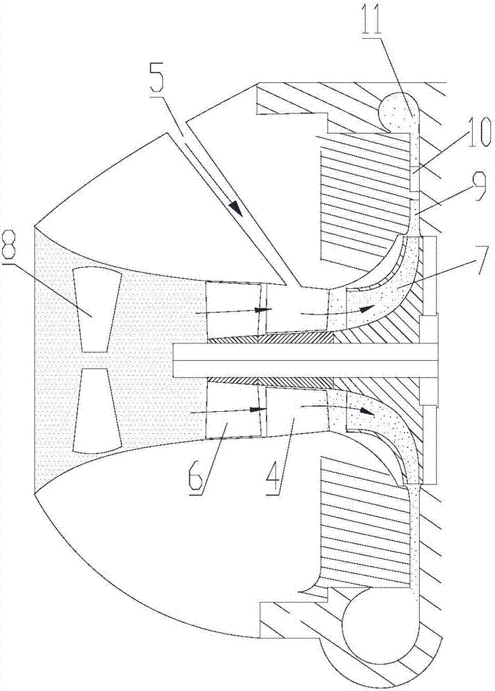
[0023] The centrifugal refrigerating compressor in the prior art adopts two-stage centrifugal impellers for compression and air supplementation in the middle. After the refrigerant is compressed by the first-stage impeller, it needs to be expanded by the diffuser, and then returned to the inlet of the second-stage impeller after passing through the diversion stage of the reflux device. The direction and size of the mainstream velocity are inconsistent, resulting in a large mixing loss.

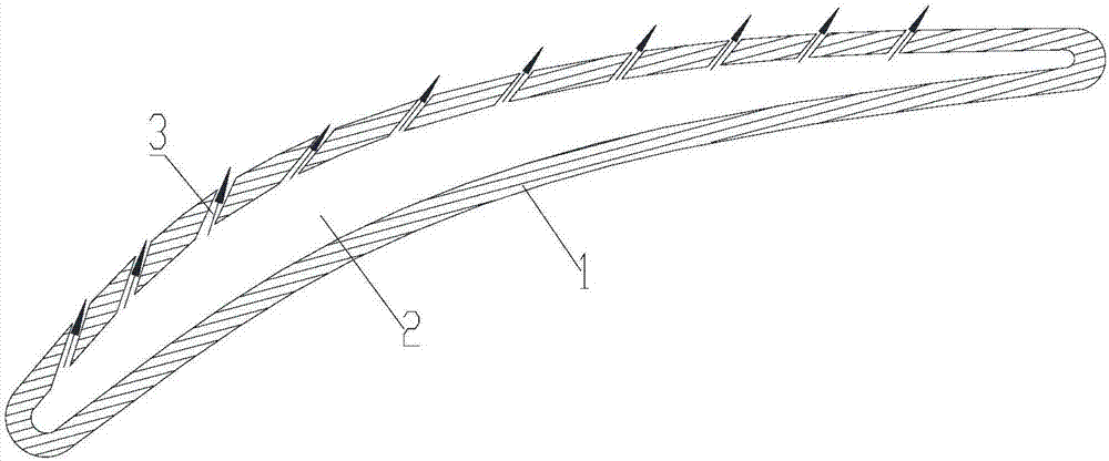
[0024] An embodiment of the present invention provides a stator vane, comprising: a vane body 1 , a cavity 2 is formed inside the vane body 1 , and an air supply hole 3 is formed on the vane body 1 . Preferably, the air supply holes 3 are arranged on the suction surface of the blade body 1 .

[0025]...


PUM


Abstract

The invention discloses a stator blade, a compressor structure and a compressor. The stator blade comprises a blade body in which an empty cavity is formed, wherein air supplementing holes are formed in the blade body. According to the stator blade, supplemented air is in a form of jet flow on a suction surface of the stator blade, so that a low-speed and low-energy area formed by the suction surface can be removed by means of blowing, and as a result, the loss due to air doping and mixing in air supplementing can be decreased, and the aerodynamic efficiency of a centrifugal compressor is improved.

Description

technical field [0001] The invention relates to the field of compressors, in particular to a stator vane, a compressor structure and a compressor. Background technique [0002] In the centrifugal refrigeration compressor, since the refrigerant is compressed, the temperature will rise sharply. At high temperature, the gas specific volume is very large. Under the condition of ensuring the same cooling capacity, the energy consumption of the compressor will increase sharply. In order to reduce the power consumption of the compressor and increase the refrigeration capacity, a multi-stage compression refrigeration cycle is commonly used. [0003] The most widely used at present is the "two-stage compression intermediate incomplete cooling refrigeration cycle" with a flash vapor separator (commonly known as an economizer). The two-stage compression refrigeration cycle is to mix the flash steam separated from the economizer with the exhaust gas from the low-stage compression, whic...

Claims


Application Information

Patent Timeline
Patent Type & Authority Applications(China)
IPC IPC(8): F04D29/54F04D29/68F04D17/02
CPCF04D17/025F04D29/542F04D29/684F04D29/444F04D29/544F05D2240/124F05D2250/291F01D5/147F01D9/065F04D19/002F04D29/563
Inventor 刘增岳钟瑞兴雷连冬陈玉辉蒋楠欧阳鑫望蒋彩云周义
Owner GREE ELECTRIC APPLIANCE INC OF ZHUHAI
Learn More