Shell and tube heat exchanger with novel baffle plates

A technology of baffles and heat exchangers, which is applied in the field of heat exchange, can solve the problems of reducing the speed of the mainstream, reducing the heat exchange efficiency, and unfavorable heat transfer, so as to reduce the heat exchange area, eliminate the flow dead zone, and achieve medium heat exchange uniform effect

Pending Publication Date: 2017-09-01
SHANDONG UNIV OF SCI & TECH
View PDF0 Cites 4 Cited by
  • Summary
  • Abstract
  • Description
  • Claims
  • Application Information

AI Technical Summary

Problems solved by technology

However, there are still some problems in the traditional bow-shaped baffles: ①The junction between the baffles and the shell is prone to local flow dead zones, which reduces the heat transfer efficiency and is easy to scale; ②The gap between the baffles and the shell wall There is a leakage flow between them, which not only reduces the velocity of the mainstream, but also produces a large temperature distortion, which is very unfavorable to heat transfer.
③ There is a gap between the outermost tube of the tube bundle and the shell, which will generate a large bypass leakage flow and reduce the effective mass flow across the tube bundle

Method used


Image

  • Shell and tube heat exchanger with novel baffle plates
  • Shell and tube heat exchanger with novel baffle plates
  • Shell and tube heat exchanger with novel baffle plates

Examples


Embodiment Construction

[0024] The following will clearly and completely describe the technical solutions in the embodiments of the present invention with reference to the accompanying drawings in the embodiments of the present invention. Obviously, the described embodiments are only some, not all, embodiments of the present invention. Based on the embodiments of the present invention, all other embodiments obtained by persons of ordinary skill in the art without making creative efforts belong to the protection scope of the present invention.

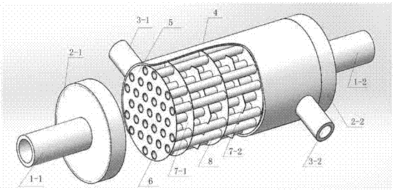
[0025] exist figure 1 Among them, the shell (4) is sealed by the left head (2-1) and the right head (2-2), and the tube side inlet (1-1) and the tube side outlet (1-2) are respectively located in the left head (2-1) and the right head (2-2), the shell side inlet (3-1) and the shell side outlet (3-2) are respectively located at the upper left and lower right of the shell (4), and the tube sheet ( 5) Located on the left and right end surfaces of the shell (1), ...


PUM


Abstract

The invention discloses a shell-and-tube heat exchanger with a new type of baffle, comprising a tube-side inlet, a tube-side inlet, a left head, a right head, a shell-side inlet, a shell-side outlet, a shell, and a tube sheet , Tube holes, circular baffles, regular hexagonal baffles, heat exchange tubes, semicircular holes and rings. Two kinds of baffles are alternately placed in the shell, among which there is a circular ring with a diameter 5-6 times the outer diameter of the heat exchange tube in the middle of the circular baffles for the shell-side medium to pass through, and the edge tube holes of the circular baffles and the positive six The middle tube holes of the side-shaped baffles are all opened with three semicircular small holes separated by 120°, and a small part of the shell-side medium can flow through. The heat exchanger can not only improve the heat exchange performance, but also effectively reduce the deposition of dirt on the heat exchange tube wall.

Description

technical field [0001] The invention relates to the technical field of heat exchange, in particular to a shell-and-tube heat exchanger with a novel baffle. Background technique [0002] In shell-and-tube heat exchangers, arcuate baffles are often installed to guide the shell-side fluid and avoid short circuits. At the same time, within the allowable range of pressure drop, the fluid velocity is accelerated as much as possible to enhance the turbulence of the shell-side fluid to achieve enhanced heat transfer. the goal of. However, there are still some problems in the traditional bow-shaped baffles: ①The junction between the baffles and the shell is prone to local flow dead zones, which reduces the heat transfer efficiency and is easy to scale; ②The gap between the baffles and the shell wall There is a leakage flow between them, which not only reduces the velocity of the mainstream, but also produces a large temperature distortion, which is very unfavorable to heat transfer....

Claims


Application Information

Patent Timeline
Patent Type & Authority Applications(China)
IPC IPC(8): F28D7/16F28F9/24
CPCF28D7/16F28F9/24
Inventor 杨前明王小琬闵庆喜李志刚霍达
Owner SHANDONG UNIV OF SCI & TECH
Why Eureka
Try Eureka