
A structured light parameter calibrating apparatus and method based on a front-film-plated plane mirror

A parameter calibration, plane mirror technology, applied in the field of visual measurement, can solve the problems of difficult geometric constraints to reach the micron level, difficult to obtain high-quality calibration images, and reduce the extraction accuracy of the center of the light bar, etc., to achieve fast real-time calibration, easy processing, Eliminate the effect of glass refraction

Active Publication Date: 2017-09-01
BEIHANG UNIV
View PDF9 Cites 37 Cited by
  • Summary
  • Abstract
  • Description
  • Claims
  • Application Information

AI Technical Summary

Problems solved by technology

This method requires a high-precision three-dimensional calibration target, the processing cost is high, and it is difficult to obtain high-quality calibration images due to factors such as reflection and occlusion
[0007] From the above analysis, it can be seen that the existing structured light parameter calibration methods require high-precision targets with feature points or high-precision geometrically constrained targets. Under these conditions, it is difficult to achieve the micron level of feature point position accuracy or geometric constraint accuracy, and there are certain errors in calculating the transformation matrix by using the image homography method; the laser light strip is projected on metal or ceramic targets due to strong reflection or diffuse Reflection, both reduce the extraction accuracy of the center of the light bar

Method used


Image

  • A structured light parameter calibrating apparatus and method based on a front-film-plated plane mirror
  • A structured light parameter calibrating apparatus and method based on a front-film-plated plane mirror
  • A structured light parameter calibrating apparatus and method based on a front-film-plated plane mirror

Examples


Embodiment

[0096] The camera model is Allied Vision Technologies, equipped with a Schneider optical lens with a focal length of 23mm, the image resolution is 1600×1200 pixels, the field of view of the visual sensor is about 200mm×160mm, and the measurement distance is 650mm. The laser is a single-line red laser with a wavelength of 635nm and a power of 50mw. Use front-coated flat mirrors such as Figure 4 As shown, the position accuracy of the feature points is 2um, and the position accuracy of the feature points of the plane target is 2um.

[0097] First, according to the method described in step 11, the camera internal parameter calibration result is obtained as follows:

[0098] alpha x =5174.34; α y = 5175.03; γ = 0; u 0 = 815.19; v 0 =597.72;k 1 =-0.19;k 2 =0.58

[0099] Here, α x 、α y They are the scale factors of u-axis and v-axis, or effective focal length, γ is the non-perpendicular factor of u-axis and v-axis, u 0 ,v 0 is the optical center, also known as the princi...


PUM


Abstract

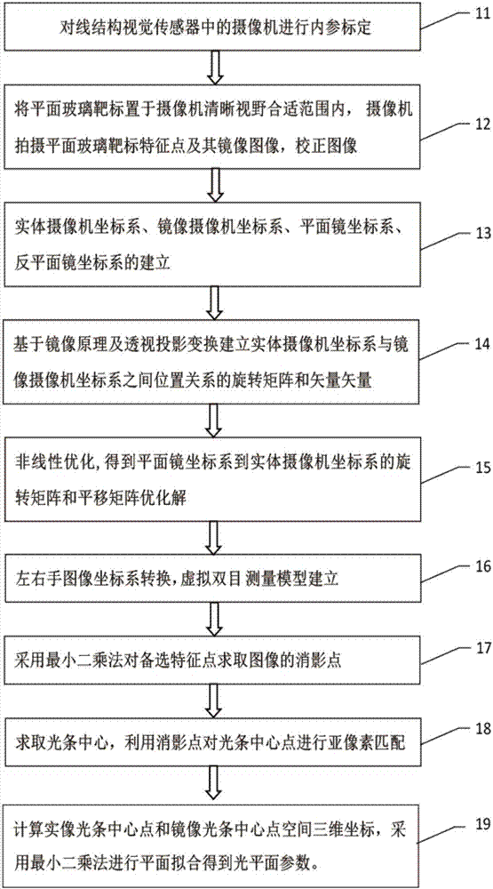
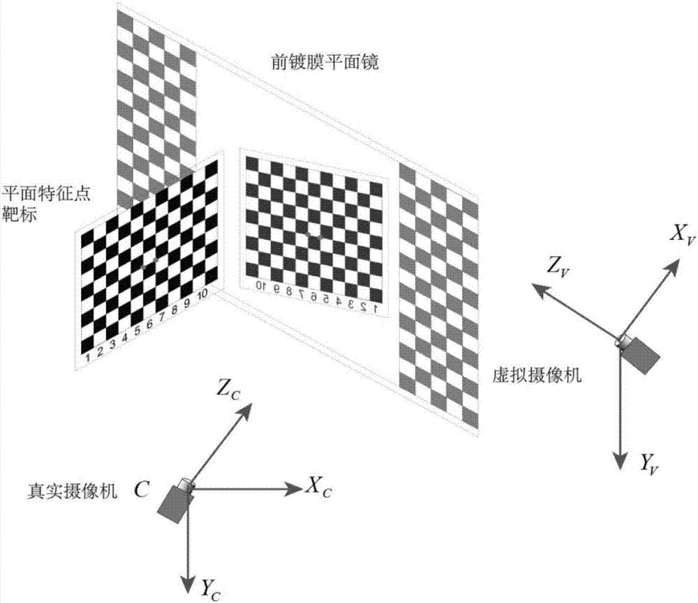
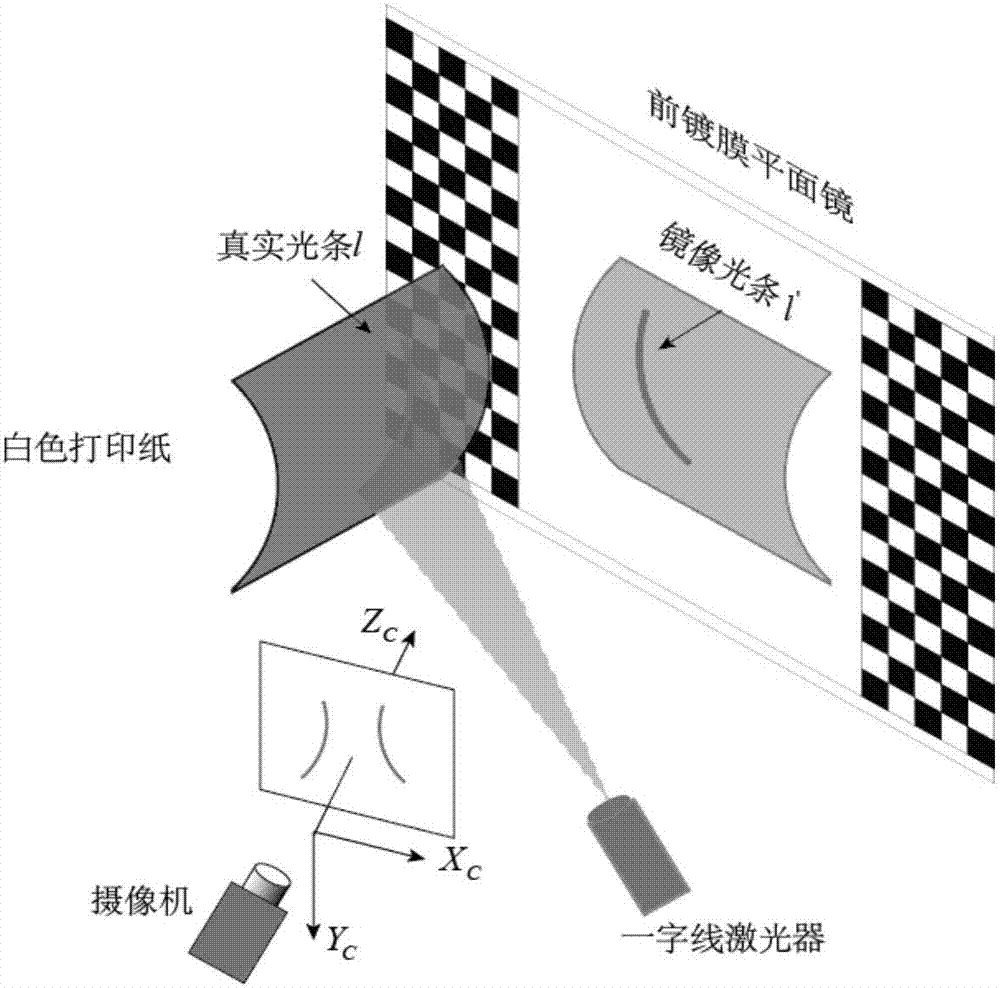
The invention discloses a structured light parameter calibrating apparatus and method based on a front-film-plated plane mirror. The method comprises the following steps: a front-film-plated plane mirror and a plane glass target are placed in front of a camera; the camera simultaneously shoots the image of the plane glass target and a mirror image of the plane glass target; a virtual binocular measurement model is established; optimal solutions of a rotation matrix from a front-film-plated plane mirror coordinate system to a camera coordinate system and a translation vector are obtained by a nonlinear optimization method; image vanishing point solving is carried out on optional feature points by the least squares method; white printing paper is placed in front of the front-film-plated plane mirror, and the camera takes the actual light bar image and the mirror image light bar image; and the center point of the light bar image is extracted to calculate the three-dimensional coordinates of matching points to solve an optical plane equation. According to the invention, the light bar quality is improved and the light bar center extraction precision is raised; feature points with the position precision of the micron order are provided to obtain more calibration points; higher calibration precision is realized; and the calibration result is more stable.

Description

technical field [0001] The invention relates to visual measurement technology, in particular to a structured light calibration device and method based on a front-coated plane mirror. Background technique [0002] Structured light 3D vision measurement has the advantages of non-contact, fast speed and moderate precision, and is widely used in industrial inspection and other fields. The calibration accuracy of the structured light vision sensor determines the final detection accuracy level. The calibration process of the line structured light vision sensor includes two aspects: camera internal parameter calibration and light plane parameter calibration. The plane equation of the light plane in the camera coordinate system is determined mainly by using the camera internal parameters and other auxiliary tools. [0003] The currently commonly used structured light sensor calibration methods mainly include: one is the free-moving target type, and one-dimensional targets, two-dime...

Claims


Application Information

Patent Timeline
IPC IPC(8): G01B21/04
CPCG01B21/042G01B11/2504G01B11/2513
Inventor 魏振忠邹伟柴斌虎
Owner BEIHANG UNIV
Learn More