
Peak value and over-peak moment tracking detection circuit

A tracking detection and circuit technology, which is applied in AC/pulse peak measurement, electrical variable measurement, current/voltage measurement, etc., can solve problems such as signal false triggering and affecting measurement results, and achieve the effect of improving accuracy and reliability

Active Publication Date: 2017-09-01
FOSHAN UNIVERSITY
View PDF13 Cites 6 Cited by
  • Summary
  • Abstract
  • Description
  • Claims
  • Application Information

AI Technical Summary

Problems solved by technology

However, the reliability of this circuit not only depends on the stability of the differential circuit, but also depends on the waveform of the detected signal. For some slowly changing signals, it is easy to cause false triggering and seriously affect the measurement results.

Method used


Image

  • Peak value and over-peak moment tracking detection circuit
  • Peak value and over-peak moment tracking detection circuit

Examples


Embodiment 1

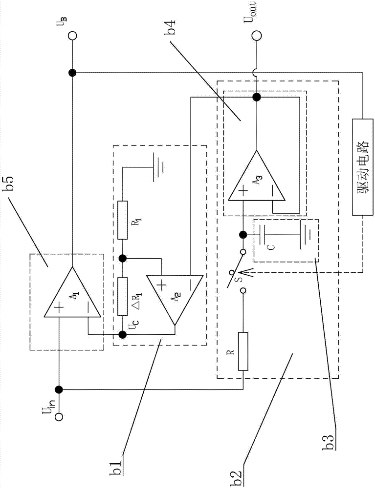
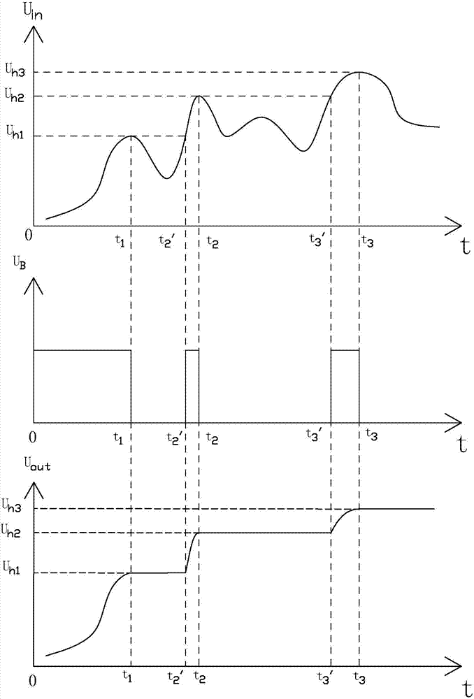
[0012] Embodiment 1, reference figure 1 , term explanation: U in is the voltage signal input by the tracking detection circuit, U B is the voltage signal output by the voltage comparator b5, U out is the voltage signal output by the sample-and-hold circuit b2, and is also the voltage signal output by the tracking detection circuit, U C is the noninverting amplifier pair U out Amplified voltage signal.

[0013] A peak and over-peak time tracking detection circuit, comprising: a voltage comparator b5, a non-inverting amplifier b1, a sample and hold circuit b2, and a drive circuit, and the sample and hold circuit b2 includes: a resistor R, a voltage follower b4, and a controlled switch S , holding circuit b3, the holding circuit b3 is composed of a capacitor C, one end of the capacitor C is connected to the non-inverting input end of the voltage follower b4 and the other end of the controlled switch S, and the other end of the capacitor C Connected to ground, when the contro...


PUM


Abstract

The invention discloses a peak value and over-peak moment tracking detection circuit which comprises a voltage comparator, a noninverting amplifier, a sampling retention circuit and a driving circuit, wherein the sampling retention circuit comprises a resistor, a voltage follower, a controlled switch and a retention circuit; the voltage follower follows voltage of the retention circuit, namely output voltage of the voltage follower is equal to that of the retention circuit; the voltage comparator compares an output voltage signal of the noninverting amplifier with a voltage signal Uin input by a tracking detection circuit; a comparison result is output through the voltage comparator to control the driving circuit; the driving circuit controls turning on or turning off of the controlled switch. The circuit directly detects and compares a voltage value of the voltage signal Uin instead of processing a waveform of the voltage signal Uin, so that the circuit is in no relation to the waveform of the voltage signal Uin; therefore, introduction of a nonlinear circuit such as a differential circuit is avoided, and the precision and the reliability of the tracking detection circuit are improved.

Description

technical field [0001] The invention relates to the technical field of electronic circuits, in particular to a peak and peak time tracking detection circuit. Background technique [0002] As a basic circuit for detecting the peak value of the voltage signal waveform, the peak voltage detection circuit is essential for nuclear radiation detectors. It is often used in high energy physics and nuclear physics energy spectrum measurement and time spectrum measurement. In addition, this circuit is also used in detectors that measure pressure, acceleration, and magnetic flux. In short, this circuit is generally required when converting physical or chemical quantities into electrical signals. Therefore, the peak voltage detection circuit is widely used in data sampling. In many systems, it is necessary to collect the peak value as the result value for processing. In this process, it is often necessary to obtain an accurate peak time to ensure the accuracy and reliability of the col...

Claims


Application Information

Patent Timeline
IPC IPC(8): G01R19/04G01R19/00
CPCG01R19/0038G01R19/04
Inventor 杨波
Owner FOSHAN UNIVERSITY
Learn More