
Real-time electron spectrometer based on thin film scintillator and optical fiber array

A technology of optical fiber array and electronic spectrometer, which is applied in the field of electronic spectrometer, can solve problems such as damage, achieve good shielding of electromagnetic pulses, and improve the effect of energy resolution

Inactive Publication Date: 2017-09-01
SHANGHAI JIAO TONG UNIV
View PDF5 Cites 1 Cited by
  • Summary
  • Abstract
  • Description
  • Claims
  • Application Information

AI Technical Summary

Problems solved by technology

However, in the laser plasma physics experiment, the experimental process will excite strong electromagnetic pulses, and sCMOS or CCD is in danger of being damaged in the environment of strong electromagnetic pulses

Method used


Image

  • Real-time electron spectrometer based on thin film scintillator and optical fiber array
  • Real-time electron spectrometer based on thin film scintillator and optical fiber array
  • Real-time electron spectrometer based on thin film scintillator and optical fiber array

Examples


Embodiment Construction

[0050] The present invention will be described in detail below in conjunction with specific embodiments. The following examples will help those skilled in the art to further understand the present invention, but do not limit the present invention in any form. It should be noted that those skilled in the art can make several changes and improvements without departing from the concept of the present invention. These all belong to the protection scope of the present invention.

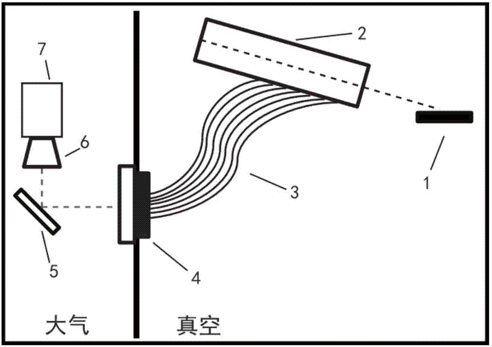
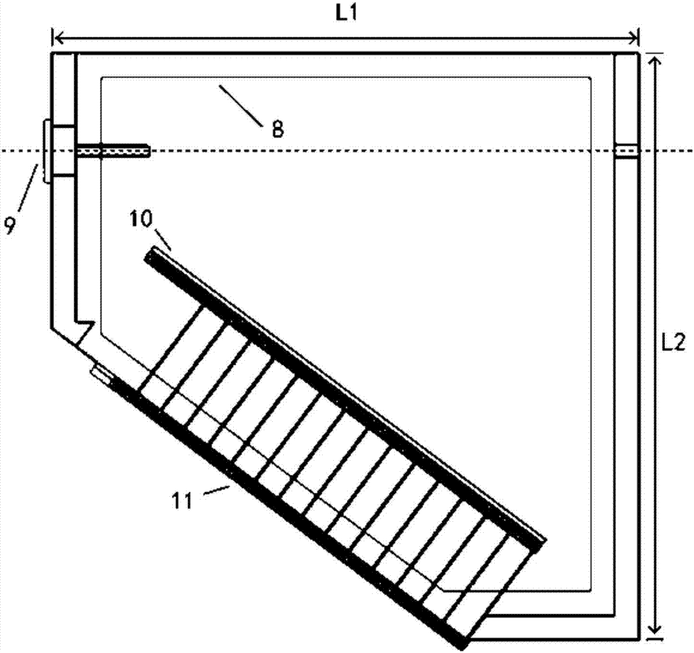
[0051] The real-time electron spectrometer based on thin film scintillator and fiber array according to the present invention includes: electron collimation device 9, uniform magnetic field device 8, scintillator 10, optical fiber line-plane conversion array and imaging system. The uniform magnetic field device 8 , the electron collimation device 9 and the scintillator 10 are arranged in the main part 2 of the electron spectrometer.

[0052]The electron spectrometer main body 2 has a coaxial hole in the...


PUM


Abstract

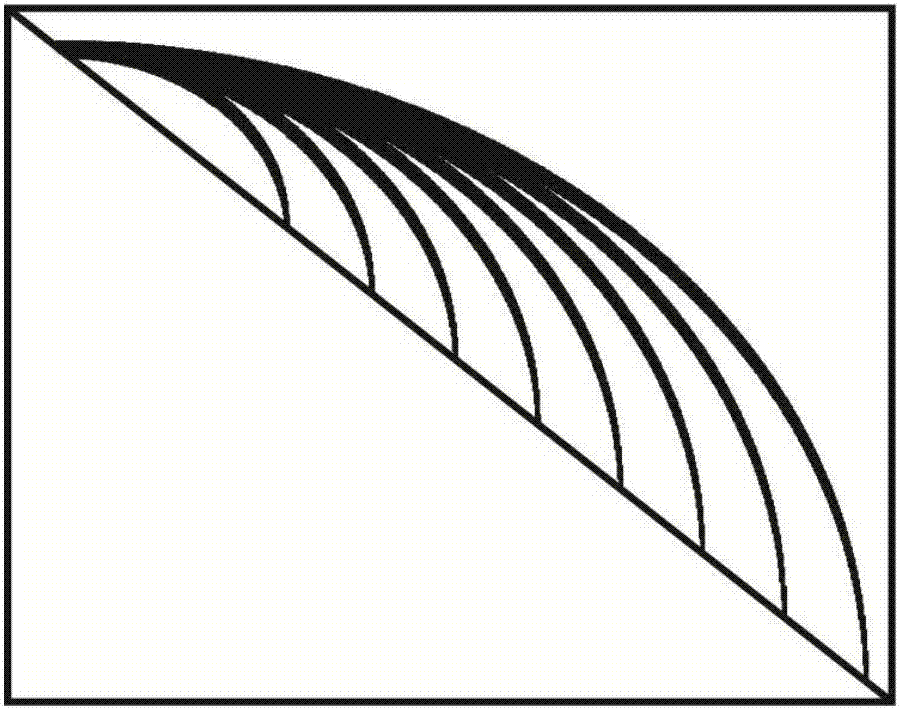
The present invention provides a real-time electron spectrometer based on a thin film scintillator and an optical fiber array. The spectrometer comprises an electron collimating device, a uniform magnetic field device, the thin film scintillator, the optical fiber line-to-plane conversion array and an imaging system; the electron collimating device, the uniform magnetic field device and the thin film scintillator are arranged in a housing; a coaxial hole in the axial direction of the electronic collimating device is formed in the housing; and the coaxial hole is used for assisting the position adjustment of the electron spectrometer. On the basis of a magnetic field deflection-based traditional electron spectrometer, the real-time electron spectrometer integrates advantages such as the real-time detection of the scintillator, low noise and flexibility of plastic optical fibers, high matching degree between the plane fiber array and the image plane of a detector. The electron spectrometer of the present invention is of simplicity and is easy to operate. The real-time electron spectrometer of the invention can diagnose and detect electrons of which the energy ranges from 0.98MeV to 4.55MeV, can be extended to higher energy bands and has a high application value in laser plasma physics.

Description

technical field [0001] The invention relates to the technical field of electron spectrometer, in particular to a real-time electron spectrometer based on a thin film scintillator and an optical fiber array. [0002] technical background [0003] Since the chirped pulse amplification technology (Chirped Pulse Amplification, CPA) was proposed by G. 20 W / cm 2 As mentioned above, the interaction between such a super-strong ultrashort pulse laser and matter will produce a large number of relativistic energy electrons. The generation and transport of these relativistic electrons is the basis of many processes of laser plasma interaction, and it is a research field in the field of high-energy energy density physics. Basic subjects. Therefore, it is extremely important to measure the energy spectrum of this relativistic electron. [0004] Electron spectroscopy is generally measured based on the principle of electron deflection in a magnetic field. The electrons are deflected by t...

Claims


Application Information

Patent Timeline
Patent Type & Authority Applications(China)
IPC IPC(8): G01T1/29
CPCG01T1/29
Inventor 葛绪雷远晓辉杨骕方远魏文青邓彦卿高健刘峰盛政明张杰
Owner SHANGHAI JIAO TONG UNIV
Learn More