PDLC membrane module, manufacturing method and display device thereof

A manufacturing method and technology of membrane components, applied in optics, instruments, nonlinear optics, etc., can solve problems such as PDLC damage

Inactive Publication Date: 2017-09-01
ZHANGJIAGANG KANGDE XIN OPTRONICS MATERIAL
View PDF10 Cites 8 Cited by
  • Summary
  • Abstract
  • Description
  • Claims
  • Application Information

AI Technical Summary

Problems solved by technology

[0009] The main purpose of the present application is to provide a PDLC film assembly, its manufacturing method and display device, to solve the problem that the PDLC film in the prior art causes damage to the PDLC when preparing the common electrode

Method used


Image

  • PDLC membrane module, manufacturing method and display device thereof
  • PDLC membrane module, manufacturing method and display device thereof
  • PDLC membrane module, manufacturing method and display device thereof

Examples


Embodiment 1

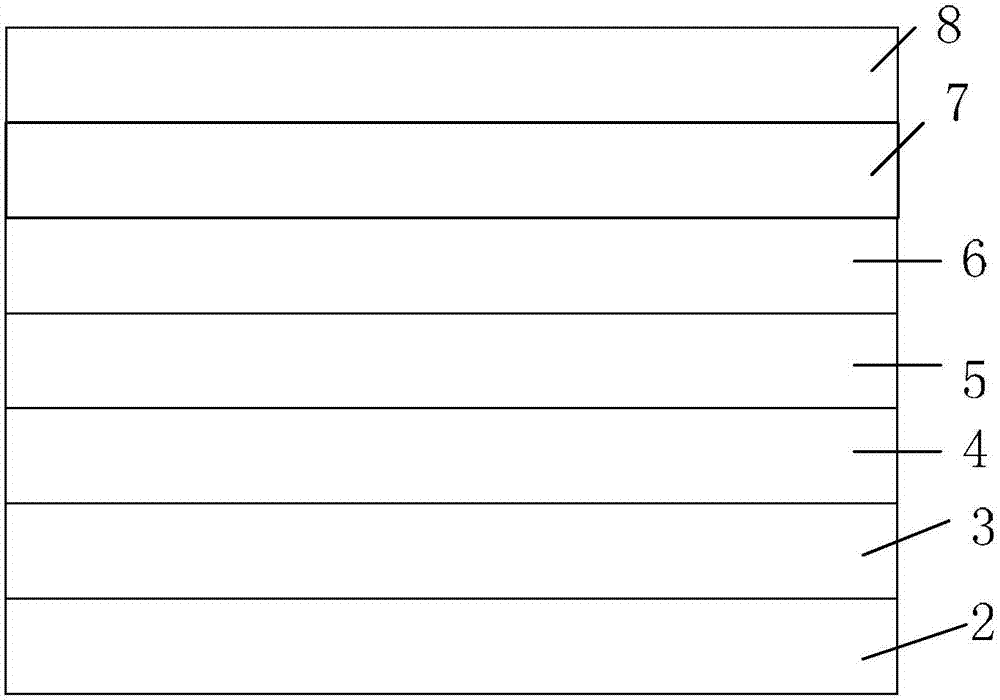
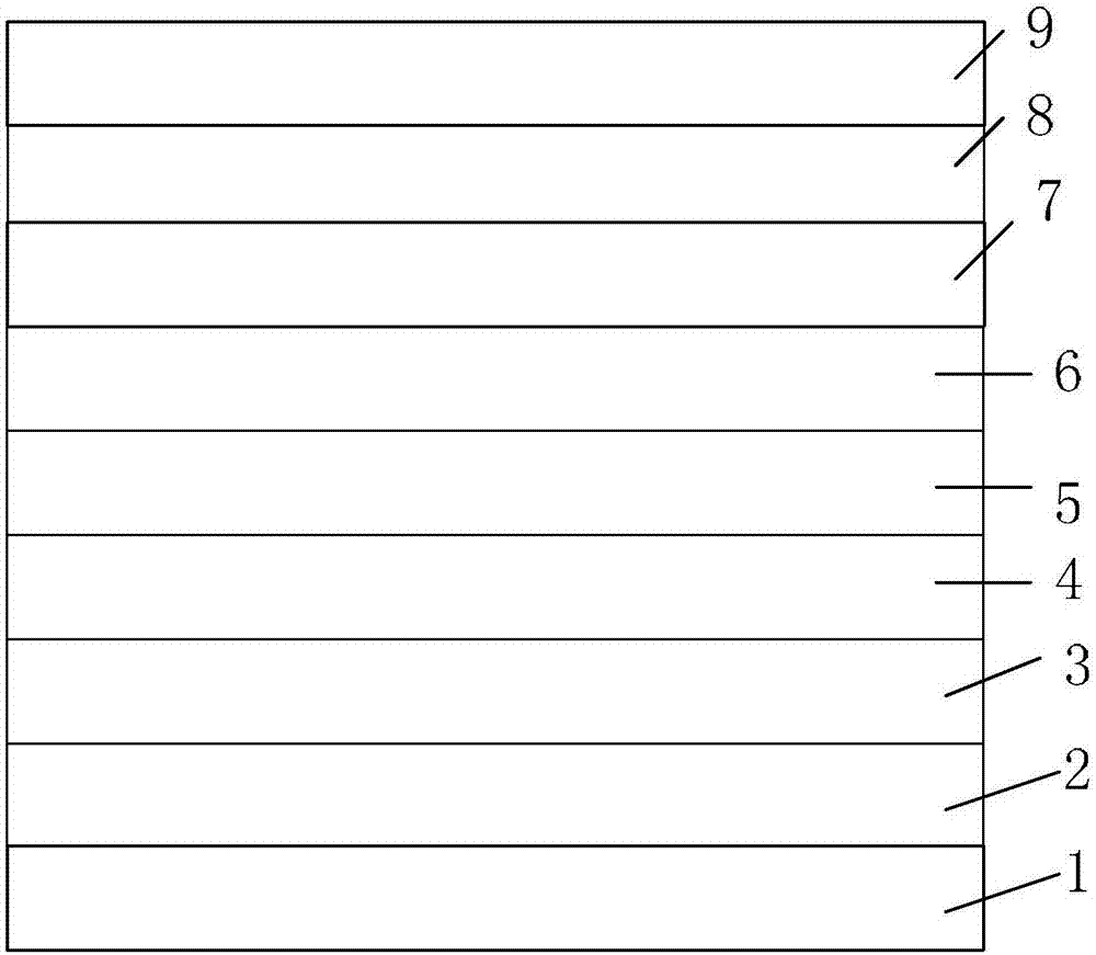
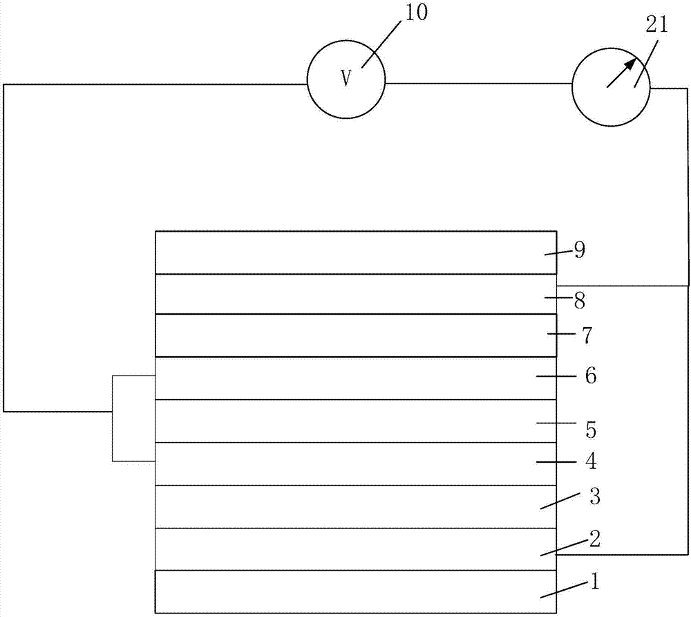
[0083] The specific structure is as Figure 4 As shown, the PDLC film assembly includes two above-mentioned PDLC films, the above-mentioned common transparent substrate layer 5 arranged between the two above-mentioned PDLC films, a power supply 10 and a first voltage regulator 21, and the two above-mentioned PDLC films are respectively the first A PDLC film and a second PDLC film, wherein the first PDLC film includes a first substrate layer 1, a first electrode layer 2, a first PDLC layer 3, and a second electrode layer 4 that are stacked in sequence, and the first PDLC layer 3 has a thickness of 10 μm, and the above-mentioned common transparent substrate layer 5 is arranged on the surface of the above-mentioned second electrode layer 4 away from the above-mentioned first PDLC layer 3; the second PDLC film is arranged on the above-mentioned common transparent substrate layer 5 far away from the above-mentioned first PDLC layer On the surface of a PDLC film, and the second PDLC...

Embodiment 2

[0089] The difference from Example 1 is that the public transparent substrate layer is a modified PS layer with a refractive index of 1.56; the thickness of the first PDLC layer is 15 μm, and the thickness of the second PDLC layer is 8 μm.

Embodiment 3

[0091] The difference from Example 2 is that the public transparent substrate layer is a modified PET layer with a refractive index of 1.50; the thickness of the first PDLC layer is 12 μm, the thickness of the second PDLC layer is 12 μm, and the polymer dispersed liquid crystal composition ( The specific formation process of PDLC is as follows:

[0092] Acrylic resin composition (48.25 g), liquid crystal BHR4030-RQ 002 (47.5 g), and spacer particles (0.25 g) having a particle diameter of 15 µm. After weighing in sequence according to the above proportions, place it in a yellow light place, then start stirring at room temperature, set the speed at 400-1000r / min, and wait for 0.5-1.5 hours after stirring. Weigh the wetting and dispersing agent TEGO670 (3g) and WO with a particle size of 30nm 3 (1g) and added in sequence, and continued to stir at room temperature for 0.5-2h to form an acrylic resin composition.


PUM

PropertyMeasurementUnit
particle diameteraaaaaaaaaa
thicknessaaaaaaaaaa
thicknessaaaaaaaaaa

Abstract

The invention provides a PDLC membrane module, a manufacturing method and a display device thereof. The PDLC membrane module comprises at least two PDLC membranes and at least one public transparent substrate layer. Each of the PDLC membranes comprises two electrode layers and a PDLC layer arranged between the two electrode layers; the public transparent substrate layer is arranged between two adjacent PDLC membranes. The two PDLC membranes in the PDLC membrane module comprise two electrode layers, and the electrode layers close to the public transparent substrate layer cannot be formed on the PDLC but on the surface of the public transparent substrate layer, so that the forming process of the electrode layers does not affect the structure of each of the PDLC layers, the performance thereof is not affected, and therefore, the performance of the display device formed thereby is not affected.

Description

technical field [0001] This application relates to the field of liquid crystal display, in particular, to a PDLC film assembly, its manufacturing method and display device. Background technique [0002] Polymer dispersed liquid crystal (PDLC for short) is an emerging photoelectric thin film material, that is, liquid crystal (LC for short) is dispersed in a polymer and undergoes polymerization under certain conditions to form liquid crystal droplets. Uniformly dispersed in a continuous polymer matrix. Due to the optical anisotropy and dielectric anisotropy of liquid crystal molecules, PDLC becomes a composite material with electro-optic response characteristics. [0003] Generally, when there is no external electric field, the LC microdroplets are uniformly dispersed in the polymer, and the nematic LC molecules in the LC microdroplets are randomly arranged. Since the effective refractive index of the LC droplet does not match the refractive index of the polymer at this time...

Claims


Application Information

Patent Timeline
Patent Type & Authority Applications(China)
IPC IPC(8): G02F1/1334G02F1/1333G02F1/1343
CPCG02F1/1333G02F1/1334G02F1/134309
Inventor 杨茂义陈明源丁清华
Owner ZHANGJIAGANG KANGDE XIN OPTRONICS MATERIAL
Why Eureka
Try Eureka