Rail heat treatment device and heat treatment method

A heat treatment device and rail technology, applied in heat treatment furnaces, heat treatment equipment, furnaces, etc., can solve the problems of complex structure and complicated operation, and achieve the effects of reasonable structure, convenient use and improved strength.

Active Publication Date: 2019-07-12
武汉钢铁有限公司
View PDF6 Cites 0 Cited by
  • Summary
  • Abstract
  • Description
  • Claims
  • Application Information

AI Technical Summary

Problems solved by technology

The current rail air spray or spray cooling device has complex structure and cumbersome operation

Method used


Image

  • Rail heat treatment device and heat treatment method
  • Rail heat treatment device and heat treatment method
  • Rail heat treatment device and heat treatment method

Examples


Embodiment 2

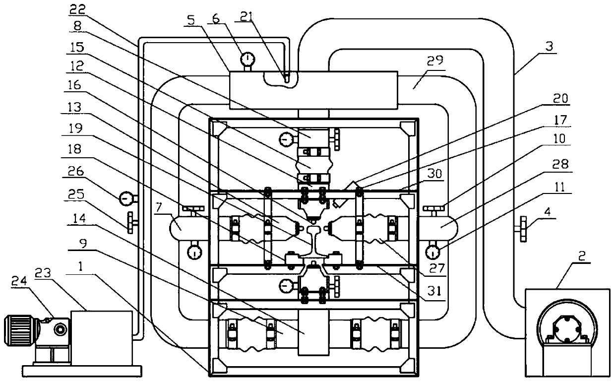
[0040] Embodiment 2 is different from Embodiment 1: the diameter of the high-temperature atomizing nozzle 21 is 3mm, the aperture of the nozzle in the first nozzle 16 is 8mm, and the distance between adjacent nozzles is 20mm, the nozzle of the first nozzle 16 of the upper and lower bellows The distance from the surface of the rail 19 is 30 mm, and the vertical distance between the center line of the nozzles of the first nozzles 16 of the left and right bellows and the plane of the rail head is 10 mm.

[0041] Turn on the air compressor 2, and by adjusting the main control valve 4 and the sub-control valve 10, control the wind pressure in the pressure-stabilizing bellows 5 to 25KPa, the wind pressure in the left and right bellows to 15KPa, the wind pressure in the upper bellows 12 to 16KPa, and the wind pressure in the lower bellows 14. Pressure is 15KPa, close air compressor 2. Place the steel rail 19 in the austenitic state on the loading platform 18 by using a mechanical fix...

Embodiment 3

[0042] Embodiment 3 is different from Embodiment 1 in that: the diameter of the high-temperature atomizing nozzle 21 is 1.5 mm, the aperture of the nozzle in the first nozzle 16 is 5 mm, the distance between adjacent nozzles is 15 mm, and the diameter of the first nozzle 16 of the upper and lower bellows The distance between the nozzle and the surface of the rail 19 is 40mm, and the vertical distance between the center line of the nozzle of the first nozzle 16 of the left and right bellows and the rail head plane is 12mm.

[0043] Turn on the air compressor 2, and by adjusting the main control valve 4 and sub-control valve 10, control the wind pressure in the pressure-stabilizing bellows 5 to 40KPa, the wind pressure in the left and right bellows to 25KPa, the wind pressure in the upper bellows 12 to 30KPa, and the wind pressure in the lower bellows 14. Pressure is 20KPa, close the air compressor 2. Place the steel rail 19 in the austenitic state on the loading platform 18 by ...

Embodiment 4

[0044] Embodiment 4 is different from Embodiment 1 in that the diameter of the high-temperature atomizing nozzle 21 is 2mm, the aperture of the nozzle in the first nozzle 16 is 7mm, and the distance between adjacent nozzles is 30mm, and the nozzles of the first nozzle 16 of the upper and lower bellows The distance from the surface of the rail 19 is 20 mm, and the vertical distance between the center line of the nozzles of the first nozzles 16 of the left and right bellows and the plane of the rail head is 13 mm.

[0045] Turn on the air compressor 2, and by adjusting the main control valve 4 and the sub-control valve 10, control the wind pressure in the pressure-stabilizing bellows 5 to 40KPa, the wind pressure in the left and right bellows to 30KPa, the wind pressure in the upper bellows 12 to 25KPa, and the wind pressure in the lower bellows 14. Pressure is 25KPa, close air compressor 2. Place the steel rail 19 in austenitic state on the loading platform 18 by using a mechan...


PUM

PropertyMeasurementUnit
lengthaaaaaaaaaa

Abstract

The invention discloses a steel rail heat treatment device. The steel rail heat treatment device comprises a heat treatment mechanism, a water supply mechanism, a gas supply mechanism, a main frame and a steel rail holding mechanism for holding a steel rail. The heat treatment mechanism comprises a pressure-stabilized air bellow, the pressure-stabilized air bellow is connected with an upper air bellow, a lower air bellow, a left air bellow and a right air bellow through a small vent pipe correspondingly, and first nozzles are arranged on the upper air bellow, the lower air bellow, the left air bellow and the right air bellow correspondingly; the first nozzle of the upper air bellow is arranged over the steel rail, the first nozzle of the lower air bellow is arranged under the steel rail, and the central axes of the first nozzle of the upper air bellow and the first nozzle of the lower air bellow coincide with the central axis of the steel rail; the first nozzle of the left air bellow and the first nozzle of the right air bellow are symmetrically arranged on the two sides of the steel rail; the water supply mechanism and the gas supply mechanism are connected with the pressure-stabilized air bellow correspondingly, and the steel rail holding mechanism is arranged in the main frame. The invention further provides a steel rail heat treatment method. The steel rail heat treatment device and the heat treatment method are easy, the operation is convenient, and the heat treatment effect of the steel rail can be ensured.

Description

technical field [0001] The invention belongs to the technical field of metal heat treatment equipment, and in particular relates to a rail heat treatment device and a heat treatment method. Background technique [0002] With the promotion of the "high-speed passenger transportation and heavy-duty freight" mode of my country's railways, the speed, traction weight, transportation density and total annual passing weight of railways continue to increase. The strength of ordinary hot-rolled rails is no longer enough to meet the new requirements of railway development. The frequency of damage increases, especially contact fatigue damage such as fish scale damage and peeled off blocks of the rail in the curved section is more serious. For this reason, the railway department requires the use of high-strength, high wear-resistant and anti-contact fatigue rails to reduce the occurrence of rail damage and increase its service life. [0003] Domestic and foreign research and practical e...

Claims


Application Information

Patent Timeline
Patent Type & Authority Patents(China)
IPC IPC(8): C21D9/04
CPCC21D9/0062C21D9/04C21D2211/009
Inventor 费俊杰周剑华吴杰周桂峰朱敏郑建国王瑞敏徐志东
Owner 武汉钢铁有限公司
Why Eureka
Try Eureka