
Construction method of post-cast tooth groove connecting assembling type roof

A construction method and prefabricated technology, applied in the direction of floors, building components, buildings, etc., can solve the problems of increasing the size and reinforcement of beams and columns, the impact of seasons and climates, and the impact of the environment, and achieve reliable connection and transmission. Strength, high degree of industrialization, and the effect of reducing self-weight

Inactive Publication Date: 2017-09-05
TIANJIN UNIV RES INST OF ARCHITECTRUAL DESIGN & URBAN PLANNING +1
View PDF10 Cites 6 Cited by
  • Summary
  • Abstract
  • Description
  • Claims
  • Application Information

AI Technical Summary

Problems solved by technology

On the one hand, in the structural design, it is often assumed that the in-plane rigidity of the floor slab is infinite, and the slab has no deformation in the plane. Therefore, the current prefabricated laminated slab needs to pour a layer of concrete surface layer with a thickness of not less than 50 mm on the prefabricated floor slab to ensure the integrity of the floor slab. performance and rigidity in the plane of the slab to ensure the formation of an assembled monolithic floor and roof structure; The inertial force under the earthquake action increases, which is unfavorable for the structure's earthquake resistance
In addition, since the laminated layer concrete of the prefabricated laminated slabs needs to be post-cast during construction, there are a large number of wet operations on site, requiring formwork and supports, complex operations, long construction periods, great influence by seasons and climates, high resource consumption, and environmental impact. Greater impact

Method used


Image

  • Construction method of post-cast tooth groove connecting assembling type roof
  • Construction method of post-cast tooth groove connecting assembling type roof
  • Construction method of post-cast tooth groove connecting assembling type roof

Examples


Embodiment Construction

[0045] In order to further understand the invention content, characteristics and effects of the present invention, the following examples are given, and detailed descriptions are as follows in conjunction with the accompanying drawings:

[0046] Please refer to the accompanying drawings, a construction method for post-cast tooth groove connection prefabricated roof, the following steps are adopted:

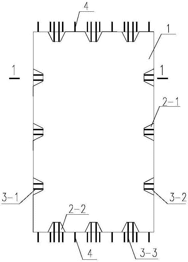
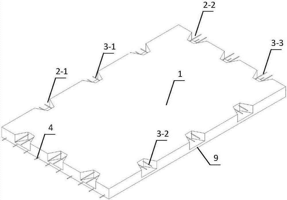
[0047] 1) The precast concrete slab 1 is processed and manufactured in the component processing plant, and the slab end and slab side of the precast concrete slab 1 are provided with tooth grooves, and the slab side tooth groove 2-1 and the slab end tooth groove 2-2 are all provided with The bottom plate 9 is provided with embedded slab side connectors in the slab side alveolar 2-1, and the embedded slab side connectors on the side of the prefabricated concrete slab 1 used to connect with the floor beams are horizontally outstretched Embedded plate side connecting reinforcement I ...


PUM


Abstract

The invention discloses a construction method of a post-cast tooth groove connecting assembling type roof. The method comprises the following steps: 1) processing precast concrete planks in a component processing factory; 2) splitting and abutting the precast concrete planks and the precast concrete planks and a floor beam to form four types of splitting abutting structures; 3) connecting embedded connectors at the split abutted parts; 4) pouring concrete in a post-cast area. Compared with currently-used prefabricated composite concrete plank, the method has the advantages that the roof constructed by the method is free from a post-cast layer, and the concrete is poured in the tooth groove type post-cast area between the planks or between the planks and the floor beam, therefore, the roof and the whole structure are sufficient in rigidity and high in earthquake proofing performance; the post-cast layer, a die plate and a support are not required, so that the construction speed can be effectively increased; the field wet works can be decreased; the dead weight of the roof can be reduced; the earthquake proofing performance of the structure can be improved.

Description

technical field [0001] The invention relates to the construction field of prefabricated assembled buildings, in particular to a construction method for post-cast tooth groove connection assembled roofs. Background technique [0002] At present, prefabricated floor slabs in the field of construction mainly include prefabricated perforated slabs, grooved slabs, and prefabricated laminated slabs. Prefabricated laminated slabs are more widely used in prefabricated structures. It is a structural form that combines prefabricated slabs with cast-in-place technology. , that is, the prefabricated slabs are produced on a large scale in the factory, transported to the construction site, and then the laminated floor slabs are formed by secondary pouring. In a building structure, an important function of the floor is to provide in-plane rigidity and strength, and to establish effective connections with vertical members and surrounding horizontal members. The floor is both an important ve...

Claims


Application Information

Patent Timeline
Patent Type & Authority Applications(China)
IPC IPC(8): E04B5/00E04B5/02
CPCE04B5/00E04B5/02
Inventor 张锡治章少华牛四欣
Owner TIANJIN UNIV RES INST OF ARCHITECTRUAL DESIGN & URBAN PLANNING
Learn More