Eureka AIR delivers breakthrough ideas for toughest innovation challenges, trusted by R&D personnel around the world.

Combined type spherical frame for inertial stabilization platform

An inertial stable platform and combined technology, applied in directions such as navigation through velocity/acceleration measurement, can solve problems such as not fundamentally solving the axial alignment accuracy, affecting the constant temperature of the inertial instrument, and the shape and position error of the shaft end surface installation , to achieve light weight, high stability, and reduce shape and position errors

Active Publication Date: 2017-09-05
BEIJING INST OF AEROSPACE CONTROL DEVICES
View PDF7 Cites 5 Cited by
  • Summary
  • Abstract
  • Description
  • Claims
  • Application Information

AI Technical Summary

Problems solved by technology

The traditional platform structure adopts a ring frame and a rectangular table body. The motor and angle / angular velocity measurement circuit are placed at the joint of the shaft end of the frame. Due to the limitation of the accommodation volume and the ring structure, the shaft end is designed as an external convex structure. In order to make each frame free If it rotates, the size of the frame needs to be increased, so it will occupy a large space for turning, and the volume is large, which cannot meet the current development trend of light and small platforms; at the same time, the platform structure adopts an open ring frame, which is greatly affected by the external temperature environment. It is easy to affect the constant temperature of the inertial instrument
[0003] In the patent "a spherical inertial stable platform" (application number: 201510945612.2), a double-layer skin frame structure is mentioned, which divides a spherical surface into two parts through the shaft end, and its advantage is to install the frame first from the inside to the outside The internal load is spliced ​​to the spherical frame. The disadvantage is that because the frame is not a whole, it will cause installation shape and position errors on the shaft end face.
In the patents "a spherical inertial stable platform with bipolar axis spherical reticulated shell structure" (application number: 201510946974.3) and "a spherical inertial stable platform with a triangular hollow structure" (application number: 201510946880.6), in order to overcome the shaft end surface installation Shape and position error, instead of splitting the spherical surface from the shaft end, it splits it from the intersection surface, which forms a 45° angle with the center points of the four shaft ends. Although this cutting method does not cause the shape and position of each shaft end surface error, but it does not fundamentally solve the axial alignment accuracy of the circumferential end faces distributed on the two hemispheres

Method used


Image

  • Combined type spherical frame for inertial stabilization platform
  • Combined type spherical frame for inertial stabilization platform
  • Combined type spherical frame for inertial stabilization platform

Examples


Embodiment 1

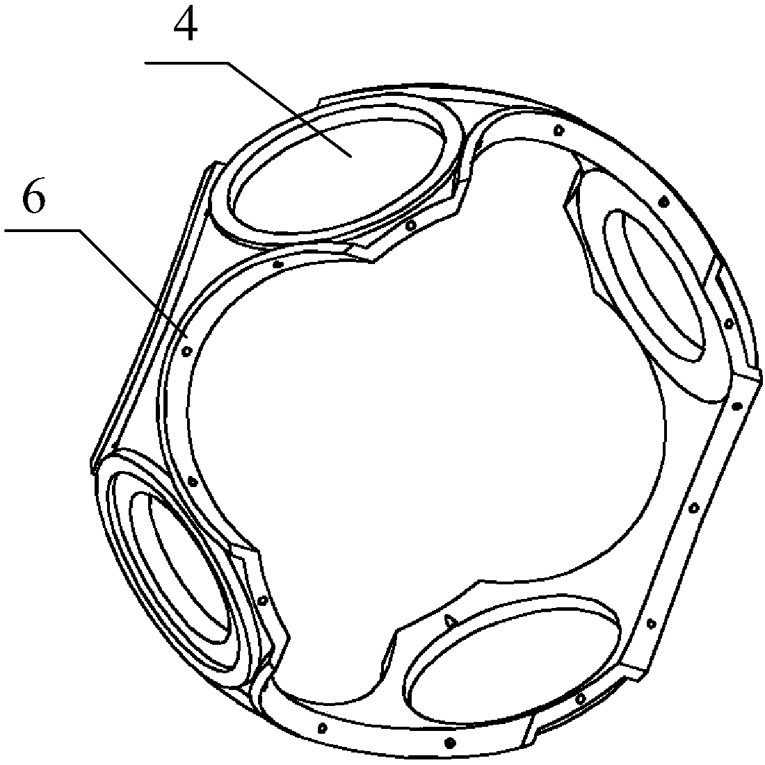
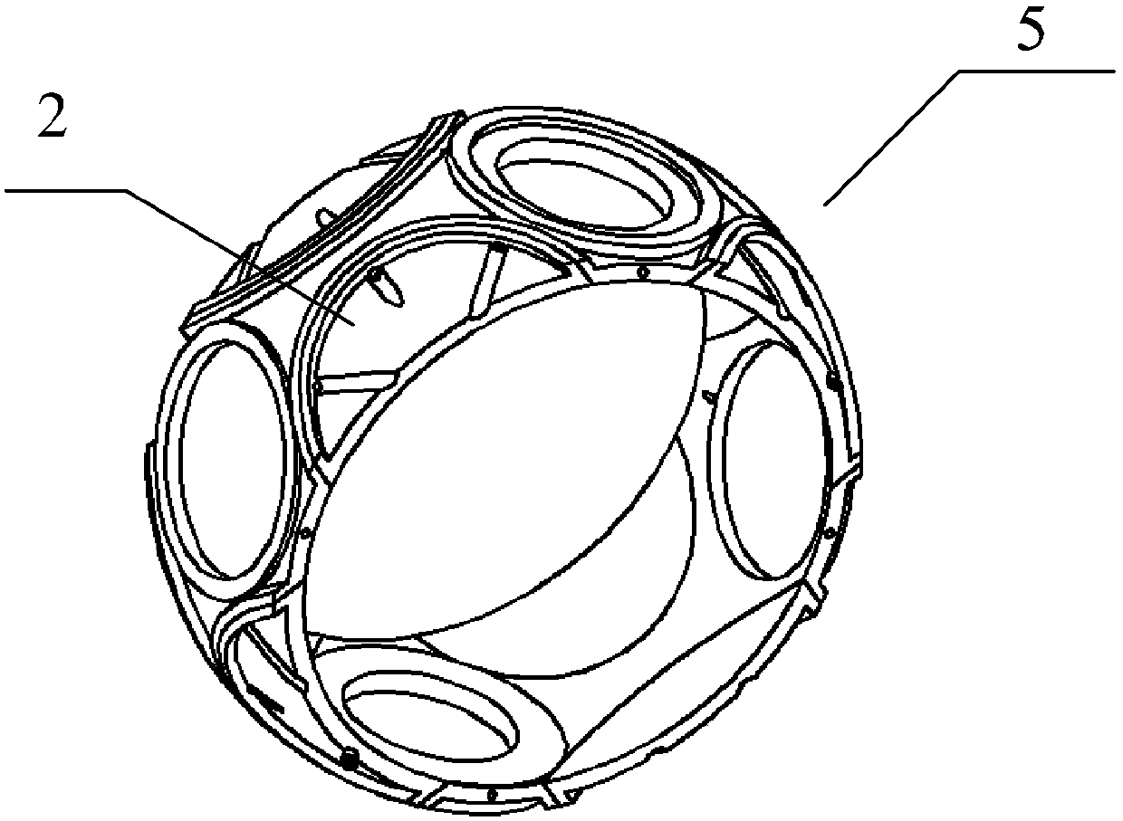
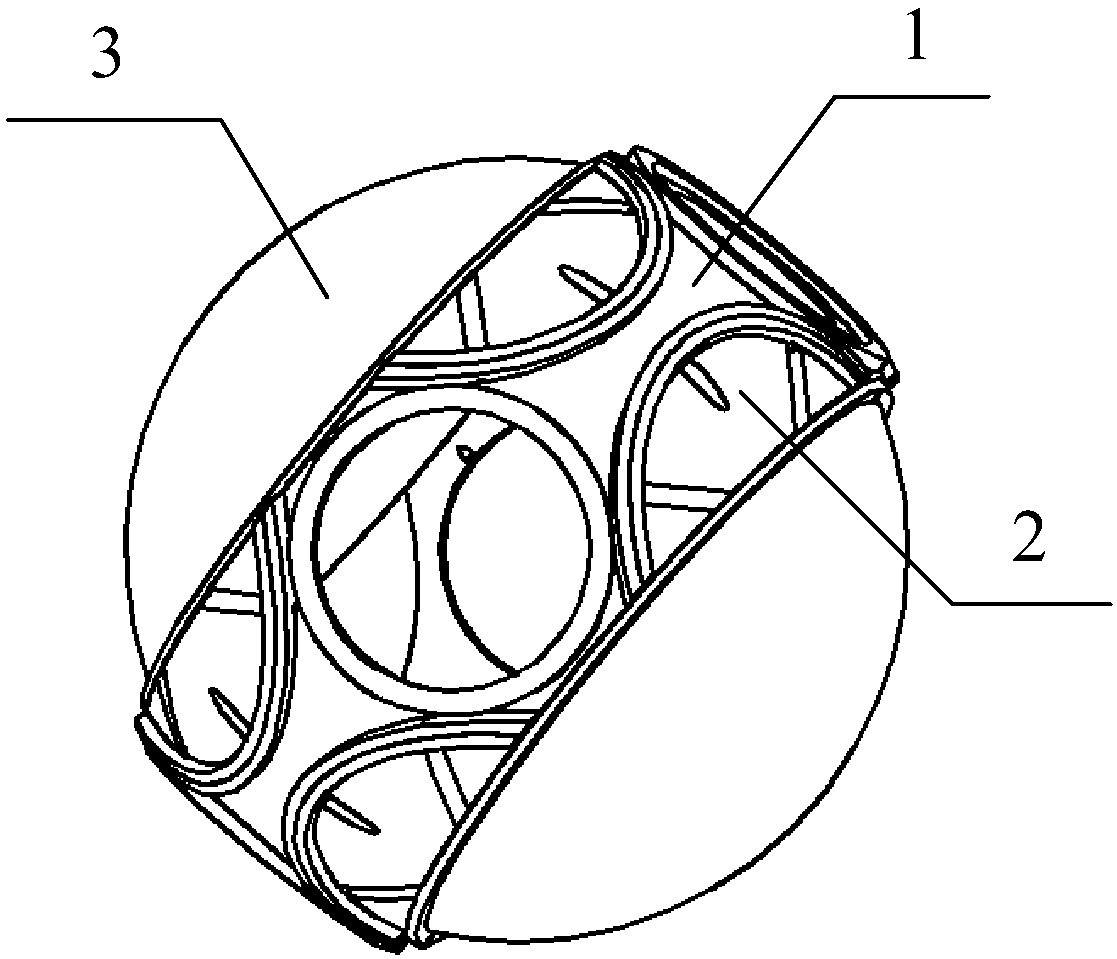
[0052] Such as figure 1 , 2 , 3, the combined spherical frame in this embodiment is a four-axis three-frame structure, and each spherical frame includes an integrated body structure 1, eight arcuate structure bodies 2 and two spherical structures 3. Among them, the surface of the ring frame of the integrated body structure 1 is evenly distributed with four shaft end element installation ports 4, and the connection line between the center points of the two opposite shaft end element installation ports 4 is the same as the other two opposite shaft end element installation ports 4 The connecting lines between the center points are perpendicular to each other, that is, the angle between two adjacent shaft end element installation ports 4 is 90°, and the connecting rod 6 connecting the adjacent two shaft end element installation ports 4 is a spherical arc surface The distance between any point on the inner surface of the spherical arc surface structure and the central point of the...


PUM


Abstract

The invention relates to a combined type spherical frame for an inertial stabilization platform, which is composed of an integrated body structure, 2N cambered structures and two spherical structures, wherein a shaft end assembly is mounted on the integrated body structure, and no splicing on the mounting surface of the shaft end assembly is ensured by adopting the integrated structure type, thereby being favorable for ensuring the mounting accuracy of the shaft end assembly and reducing the form and position error; the 2N cambered structures can be disassembled relative to the body structure so as to facilitate mounting or disassembly of effective loads in the spherical frame, thereby realizing the miniaturization of the inertial stabilization platform structure; and the two spherical structures realize the equal stiffness design of the spherical frame, thereby reducing the second-order disturbance torque caused by the non-equal stiffness design. The spherical frame provided by the invention can ensure the mounting accuracy of the shaft end assembly to the maximum limit and reduce the dynamic error, thereby increasing the torque disturbance resisting capability of the frame, effectively reducing the rotary volume occupied by the frame, and realizing high accuracy, high stability and miniaturization of the inertial stabilization platform.

Description

technical field [0001] The invention relates to a combined spherical frame of an inertial stable platform, which belongs to the field of mechanical structure design. Background technique [0002] The main function of the gyro-stabilized platform is to establish a navigation coordinate system that has nothing to do with the angular motion of the projectile (arrow) according to the given technical indicators, and provide the necessary coordinate reference for the measurement of acceleration and attitude angle. . The traditional platform structure adopts a ring frame and a rectangular table body. The motor and angle / angular velocity measurement circuit are placed at the joint of the shaft end of the frame. Due to the limitation of the accommodation volume and the ring structure, the shaft end is designed as an external convex structure. In order to make each frame free If it rotates, the size of the frame needs to be increased, so it will occupy a large space for turning, and ...

Claims


Application Information

Patent Timeline
Patent Type & Authority Applications(China)
IPC IPC(8): G01C21/18
CPCG01C21/18
Inventor 胡光龙魏宗康耿克达邓超闫文民岑志轩
Owner BEIJING INST OF AEROSPACE CONTROL DEVICES
Why Eureka
Eureka Blog
Learn More