Thrombus extraction bracket and thrombus extraction device

A technology of support force and radial support, applied in the field of medical devices, to achieve the effect of improving the success rate of thrombectomy, preventing thrombus from falling off and escaping, and avoiding distal re-embolization

Active Publication Date: 2017-09-08
MICROPORT NEUROTECH SHANGHAI
View PDF10 Cites 15 Cited by
  • Summary
  • Abstract
  • Description
  • Claims
  • Application Information

AI Technical Summary

Problems solved by technology

[0007] The purpose of the present invention is to provide a thrombectomy bracket and a thrombectomy device to solve the problem that the existing thrombectomy device fails to achieve a balance between the thrombectomy efficiency and the safety and ease of operation

Method used


Image

  • Thrombus extraction bracket and thrombus extraction device
  • Thrombus extraction bracket and thrombus extraction device
  • Thrombus extraction bracket and thrombus extraction device

Examples


Embodiment 1

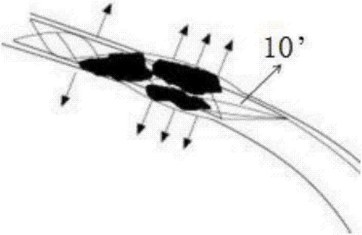
[0055] Such as Figure 4~5 , 7, and 14, the present embodiment provides a thrombectomy bracket 10, the thrombus retrieval bracket 10 is a columnar structure, and the columnar structure has two or more meshes with different mesh areas. Holes and interconnected to form a plurality of nodes of the mesh, a plurality of said nodes have two or more than two different shapes, the nodes of different shapes select a specific ratio, different node shapes and mesh area make the thrombectomy support The radial support force during expansion is less than the first force threshold F1, and the radial support force of the thrombectomy stent remains unchanged during the expansion process of the thrombectomy stent. Different node shapes and mesh areas make the radial support force of the thrombectomy stent less than the second force threshold F2 during compression, avoiding excessive radial support force, which makes the thrombectomy stent difficult to compress; and makes the thrombectomy stent...

Embodiment 2

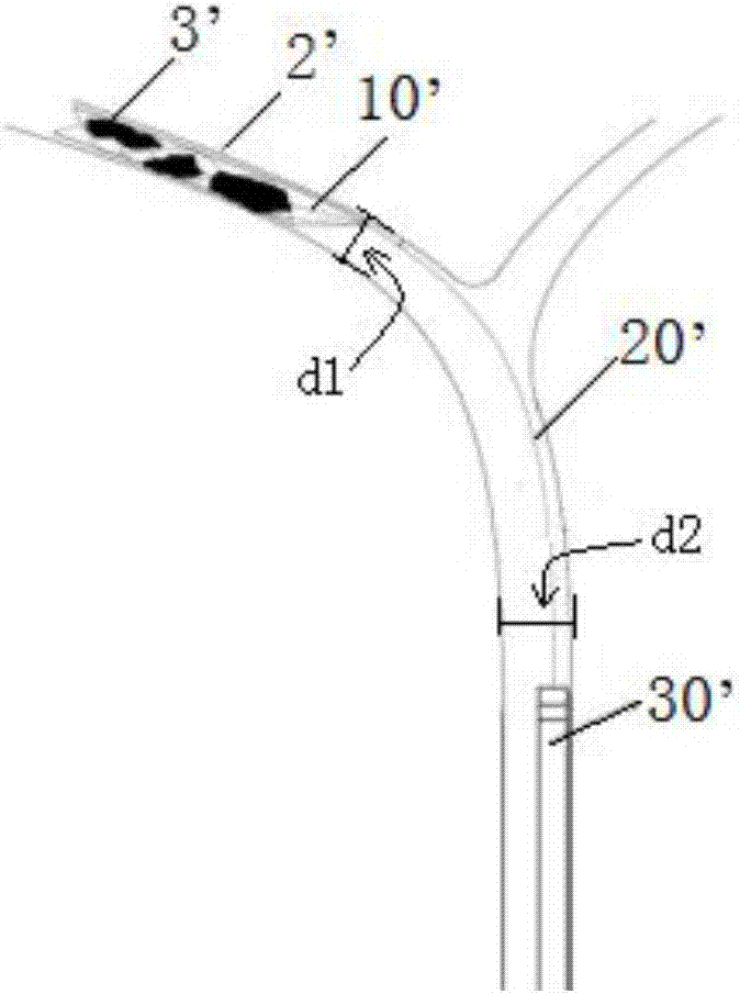
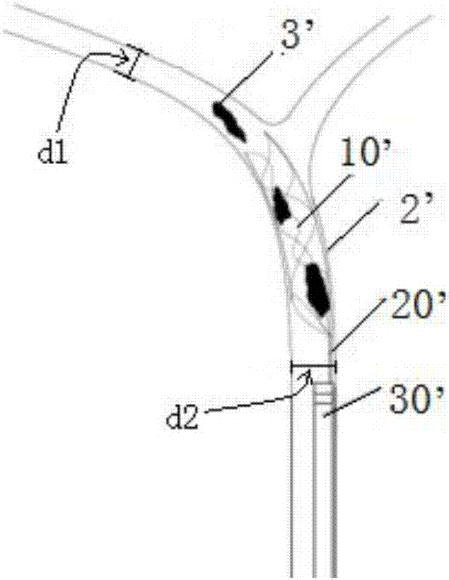
[0070] This embodiment provides a thrombectomy device, such as Figure 4~5 , 7 to 14, the thrombectomy device 1 includes the thrombectomy bracket 10 described in the previous embodiment, the guide device 20, the catheter 30 and the outer sheath 50, wherein: the thrombectomy bracket 10 is in the shape of a net column structure; the outer sheath 50 pushes the thrombectomy support 10 into the catheter 30, and the catheter 30 is used to deliver the thrombectomy support 10, and the thrombectomy support 10 is placed in the outer sheath 50 or The catheter 30 is in a compressed state, and is in an expanded state outside the outer sheath 50 or the catheter 30; the guide device 20 pushes and pulls the thrombectomy support 10, so that the thrombectomy support 10 enters and exits the thrombectomy support 10. The catheter 30 or the outer sheath 50; the outer sheath 50 is used to align with the catheter 30, and then the thrombectomy support 10 is pushed into the catheter 30 through the oute...


PUM


Abstract

The invention provides a thrombus extraction bracket and a thrombus extraction device. The thrombus extraction bracket is a net post shaped structure; an outer sheath pipe is used for pushing the thrombus extraction bracket to a catheter; the catheter is used for conveying the thrombus extraction bracket, and the thrombus extraction bracket is under a compression state in the outer sheath pipe or the catheter, and under an expanding state at outside of the outer sheath pipe or the catheter; a guiding device pushes the thrombus extraction bracket so that the thrombus extraction bracket accesses the outer sheath pipe or the catheter; the thrombus extraction bracket is the net post shaped structure, two or more than two net holes with different areas and a plurality of nodes connected mutually to form net holes are arranged on the net post shaped structure; a plurality of nodes have two or more shapes, and nodes in different shapes shall select specific ratio; different node shapes and net hole areas can make that the radial supporting force is less than the first force threshold value when the thrombus extraction bracket is expanded; moreover, the radial supporting force of the thrombus extraction bracket is unchanged during the expanding process of the thrombus extraction bracket.

Description

technical field [0001] The invention relates to the technical field of medical devices, in particular to a thrombectomy bracket and a thrombectomy device. Background technique [0002] Acute ischemic stroke is the damage of nerve tissue caused by ischemic necrosis of local brain tissue due to sudden blockage of blood flow in the brain, and it is the main disease causing death and disability in middle-aged and elderly people. With the continuous increase of the elderly population and the improvement of living standards, the incidence of cerebrovascular disease continues to increase. The recanalization of blood vessels is the key to the treatment of acute ischemic stroke. At present, the conventional methods for the treatment of acute ischemic stroke include two categories: intravascular thrombolysis and mechanical thrombectomy. [0003] Intravascular thrombolysis means that the catheter injects a thrombolytic agent into the vicinity of the lesion in the blood vessel where th...

Claims


Application Information

Patent Timeline
Patent Type & Authority Applications(China)
IPC IPC(8): A61B17/22
CPCA61B17/22A61B2017/00778A61B2017/00831
Inventor 邹秋华于海瑞刘迎苗琳莉金巧蓉谢志永
Owner MICROPORT NEUROTECH SHANGHAI
Why Eureka
Try Eureka